Eureka AIR delivers breakthrough ideas for toughest innovation challenges, trusted by R&D personnel around the world.

Fixing apparatus and image formation apparatus using same

a technology of fixing apparatus and fixing plate, which is applied in the direction of electrographic process apparatus, instruments, developers, etc., can solve the problems of slow fixing efficiency, inability to accelerate the warm-up process, and the heating roller takes longer to reach the set temperatur

Inactive Publication Date: 2007-07-03
RICOH KK
View PDF15 Cites 85 Cited by
  • Summary
  • Abstract
  • Description
  • Claims
  • Application Information

AI Technical Summary

Benefits of technology

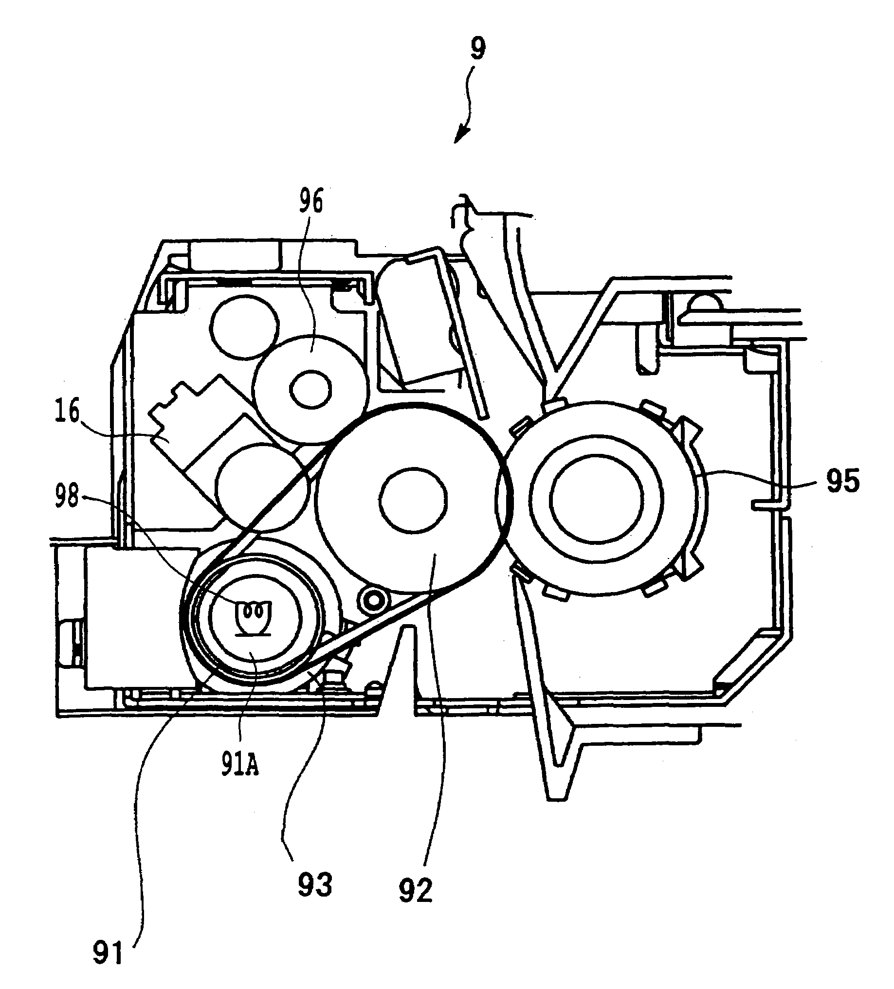
The present invention provides a fixing apparatus for fixing toner on a recording medium, which reduces heat transfer to the fixing belt during warm-up and shortens the time required for the heating roller temperature to rise. This results in faster heating and lower energy consumption. The fixing apparatus includes a heating roller, a fixing belt, a press roller, a tension roller, and an adjustment device for adjusting the contact surface area of the fixing belt on the heating roller. The invention also provides an image formation apparatus that uses this fixing apparatus, a toner used in the apparatus, and a fixing apparatus for fixing toner on a passing recording medium. The technical effects of the invention include improved printing speed, reduced energy consumption, and improved image quality.

Problems solved by technology

There has been demand in recent years for lower energy consumption and shorter standby times. However, if the temperature during standby is lowered, it takes longer for warm-up, which is how long it takes for the fixing apparatus to rise to the temperature at which fixing is possible, and this lowers fixing efficiency.
When a thin heating roller is used in order to speed up the warm-up process, heat moves to the belt and ends up being radiated while the heating roller is in the course of reaching its set temperature, and this makes it take longer for the heating roller to reach its set temperature.
When the tension is loosened, though, a few seconds are lost when the tension is reapplied, so despite the effort to minimize the excess radiation of heat, time is spent reapplying tension, so at present there is little merit to accelerating the warm-up process.

Method used


Image

  • Fixing apparatus and image formation apparatus using same
  • Fixing apparatus and image formation apparatus using same
  • Fixing apparatus and image formation apparatus using same

Examples


Embodiment Construction

[0022]An embodiment of the present invention will now be described in detail through reference to the drawings.

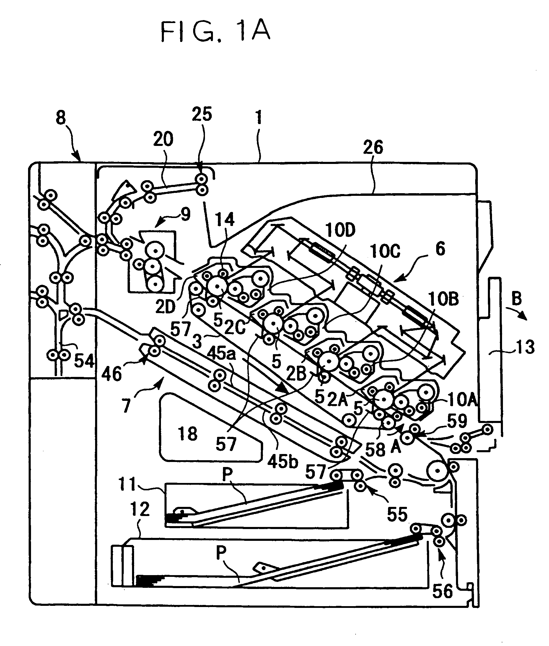
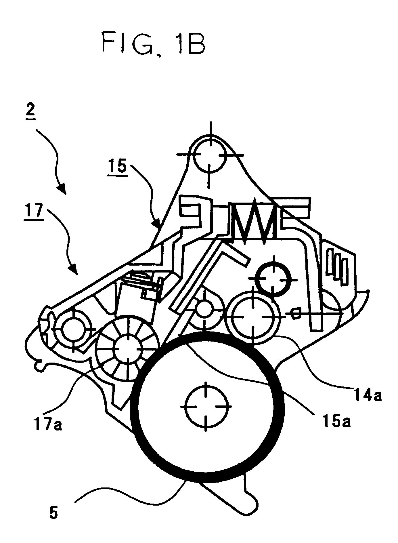
[0023]FIGS. 1A and 1B are diagrams of the simplified structure of the image formation apparatus pertaining to an embodiment of the present invention. FIG. 1A is an overall view of the image formation apparatus, and FIG. 1B is a simplified diagram of the structure of the image formation unit.

[0024]Four image formation units 2A, 2B, 2C, and 2D, each having a photosensitive member (image support), are detachably installed inside an image formation apparatus 1. A transfer apparatus 3, in which a transfer belt 3a is mounted rotatably in the direction of arrow A between a plurality of rollers, is disposed in the approximate center of the image formation apparatus 1. The photosensitive members 5 provided to the image formation units 2A, 2B, 2C, and 2D are disposed so as to be in contact with the top side of this transfer belt 3a. Developing apparatus 10A, 10B, 10C, and 10D, each o...


PUM


Abstract

It is an object of the present invention to provide a fixing apparatus with which the movement of heat to the fixing belt during warm-up is suppressed, and the time it takes for the heating roller temperature to rise can be shortened, by reducing the contact surface area between the fixing belt and the heating roller, and an image formation apparatus that makes use of this fixing apparatus, and a toner used therein. A separation member provided on the inside of the fixing belt forms a pair with a tension roller, and a switching device for switching the positions thereof switches the positions when a set temperature is detected by temperature sensing device installed on the heating roller, so that the contact surface area of the fixing belt on the heating roller is different during warm-up and during fixing.

Description

BACKGROUND OF THE INVENTION[0001]1. Field of the Invention[0002]The present invention relates to an image formation apparatus such as a copier, fax machine, or printer, and more particularly relates to a fixing apparatus that melts and solidifies toner on a recording medium such as recording paper or OHP film.[0003]2. Description of the Related Art[0004]In the fixing step with this type of image formation apparatus, a toner image on a recording medium that has been transferred from a photosensitive member (latent image support) is fixed on a recording medium, and this is an essential step in which, for example, toner is put in a molten state by heating and pressing, and the toner is made to permeate and fuse to transfer paper, a resin sheet, or another such recording medium in this molten state. Fixing methods include contact fixing methods in which the members on the heat source side are in direct contact with the toner (what is being fixed), and non-contact methods which involve a...

Claims


Application Information

Patent Timeline
Patent Type & Authority Patents(United States)
IPC IPC(8): G03G15/20G03G9/08G03G9/087
CPCG03G15/2064G03G15/2017G03G2215/2016G03G2215/2032
Inventor SATO, MASAHIKOOMURA, KENIWAYA, NAOKISHINSHI, AKIRA
Owner RICOH KK
Why Eureka
Eureka Blog
Learn More