Manometer

a manometer and gauge technology, applied in the field of manometers, can solve the problem that automatic assembly is not possible without additional means, and achieve the effect of simple automatic assembly and easy and economical production

Inactive Publication Date: 2007-07-10
FORSTER STEFFEN
View PDF11 Cites 0 Cited by
  • Summary
  • Abstract
  • Description
  • Claims
  • Application Information

AI Technical Summary

Benefits of technology

[0003]An object of the invention is the design of a manometer of the type named above, which can be easily and economically produced and which also enables simple automatic assembly.

Problems solved by technology

However, this type of mounting has the disadvantage that automatic assembly is not possible without additional means.

Method used


Image

  • Manometer
  • Manometer
  • Manometer

Examples


Embodiment Construction

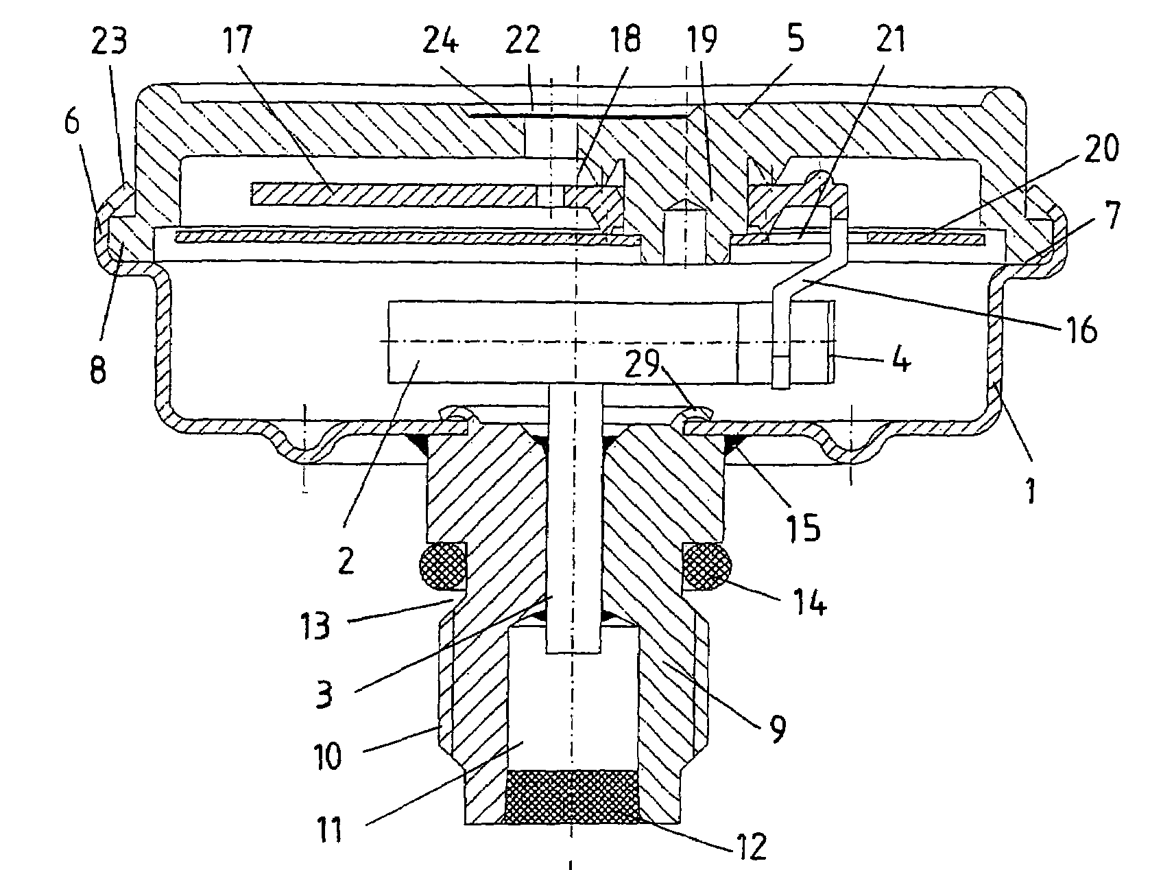
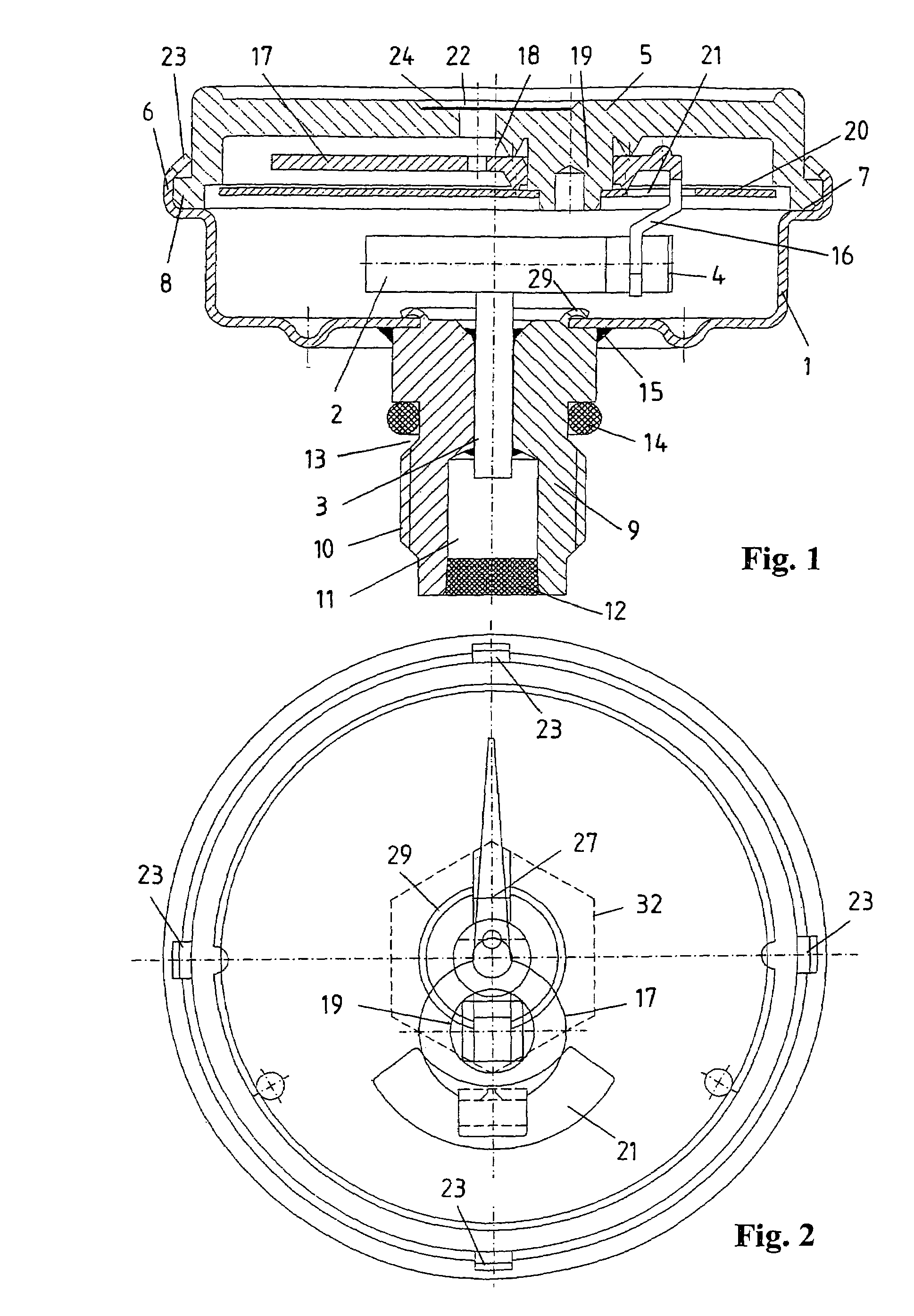
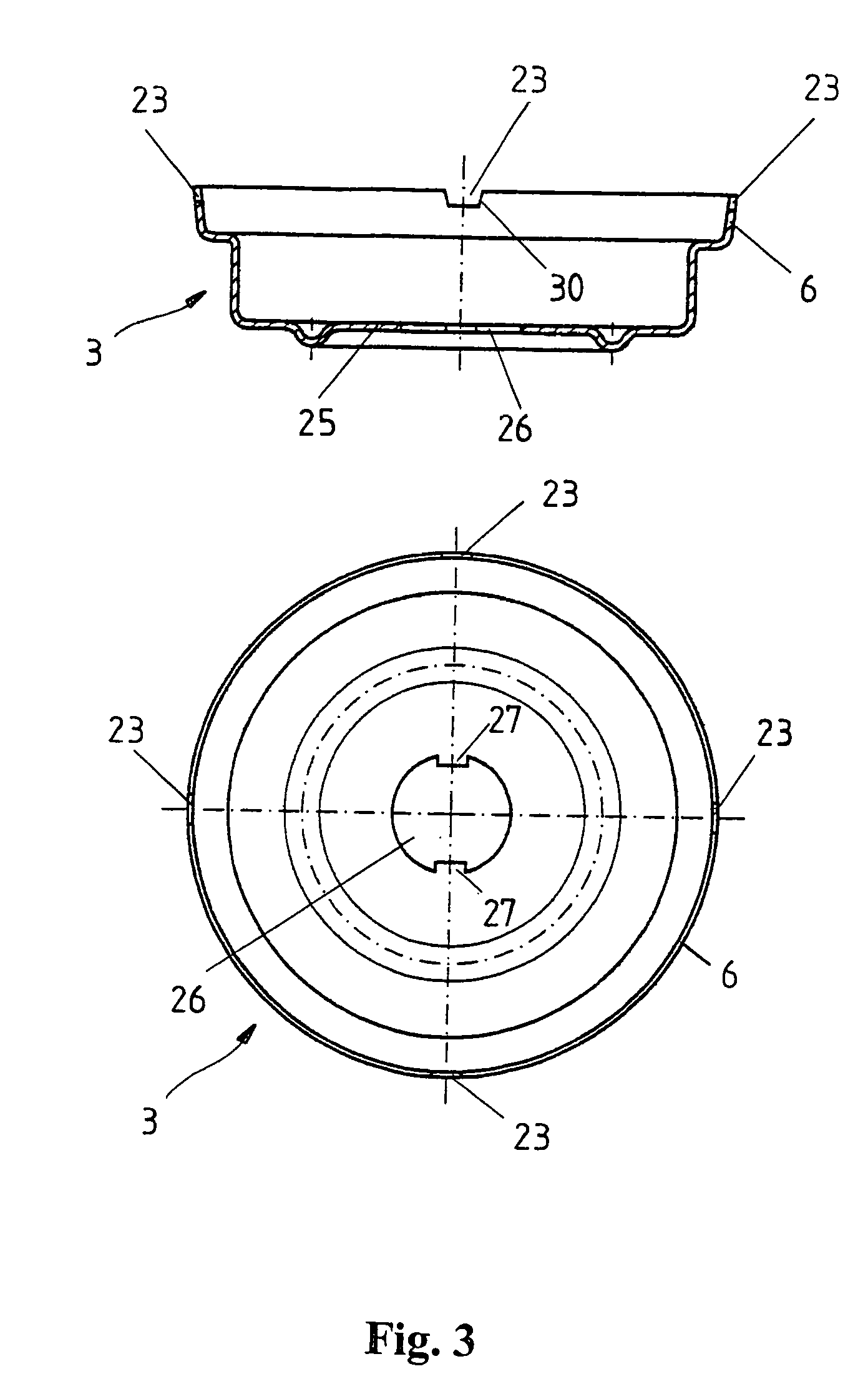
[0013]The manometer shown in FIGS. 1 and 2 in longitudinal section and a plan view contains a bowl-shaped housing 1, in which is arranged a spiral-shaped bent bourdon tube 2 with an open end 3 fixed to the housing and a freely movable closed end 4. The housing 1 is covered on its top side by a circular viewing glass 5. For fixing the viewing glass 5 to the housing 1, the housing 1, which is configured as a sheet-metal part, has on its top side a surrounding connecting piece 6 and an annular surface 7 for support of the viewing glass 5. The connecting piece 6 is flanged inwards when the manometer is assembled and presses against the viewing glass 5 on an outer annular shoulder 8, whereby this glass is held. On the bottom side of the housing 1, a connecting piece 9 shown separately in FIG. 4 is attached. The connecting piece 9 has on its outer side threads 10 for fixing the manometer in a bore of a component, e.g., a fire extinguisher, under pressure. A bore 11 connected to the open e...


PUM

PropertyMeasurementUnit
pressureaaaaaaaaaa
flexibleaaaaaaaaaa
adhesiveaaaaaaaaaa

Abstract

The invention relates to a manometer with a housing, a connecting piece rigidly connected to the housing, a bourdon tube arranged in the housing, a viewing glass fixed on the housing, and a pointer, which can rotate on the inside of the viewing glass and which is engaged with a free end of the bourdon tube, wherein the housing has on its top side a connecting piece that is bent inwardly for connecting to the viewing glass. To simplify the assembly, several cutouts distributed over the periphery are arranged in the connecting piece of the housing for engagement of an assembly tool, wherein the housing is connected to the connecting piece with a positive fit.

Description

FIELD OF THE INVENTION[0001]The invention relates to a manometer.BACKGROUND OF THE INVENTION[0002]Such a manometer is known from DE 101 23 103 A1. This has a housing with a bourdon tube arranged therein, a connecting piece rigidly connected to the housing, a viewing glass arranged on the housing, and a pointer that can rotate at the bottom side of the viewing glass. The pointer is in engagement with the free end of the bourdon tube. The connecting piece of this known manometer has threads on its outer side. The manometer is fixed, e.g., in a fire extinguisher valve, by means of these threads. The screwing on and tightening of the manometer is typically realized by means of a hexagonal head, which is provided on the outer side of the connecting piece. By means of a commercially available wrench, the manometer can then be fixed by hand. However, this type of mounting has the disadvantage that automatic assembly is not possible without additional means.SUMMARY OF THE INVENTION[0003]An ...

Claims


Application Information

Patent Timeline
Patent Type & Authority Patents(United States)
IPC IPC(8): G01L7/04
CPCG01L7/04
Inventor FORSTER, STEFFEN
Owner FORSTER STEFFEN
Why Eureka
Try Eureka