Heat sink for an electric machine and method for producing said heat sink

a technology for electric machines and heat sinks, which is applied in the direction of dynamo-electric machines, electrical devices, supports/enclosements/casings, etc., can solve the problems of complex manufacturing and/or reliable sealing of the housing used for cooling, and achieves simple design, efficient dissipation, and small installation space for electric machines.

Active Publication Date: 2019-11-12
ROBERT BOSCH GMBH
View PDF8 Cites 0 Cited by
  • Summary
  • Abstract
  • Description
  • Claims
  • Application Information

AI Technical Summary

Benefits of technology

[0005]Embodiments of the present invention can advantageously make it possible to provide a heat sink, with the aid of which heat can be efficiently dissipated from an electric machine. The heat sink can be designed in such a way that an installation space for the electric machine can be kept small. In this case, the heat sink can have a simple design and, therefore, inter alia, can be reliable and low-wear. In addition, the heat sink can be easily and economically produced.

Problems solved by technology

The manufacturing and / or reliable sealing of housings utilized for cooling can be complex and costly.

Method used


Image

  • Heat sink for an electric machine and method for producing said heat sink
  • Heat sink for an electric machine and method for producing said heat sink
  • Heat sink for an electric machine and method for producing said heat sink

Examples


Embodiment Construction

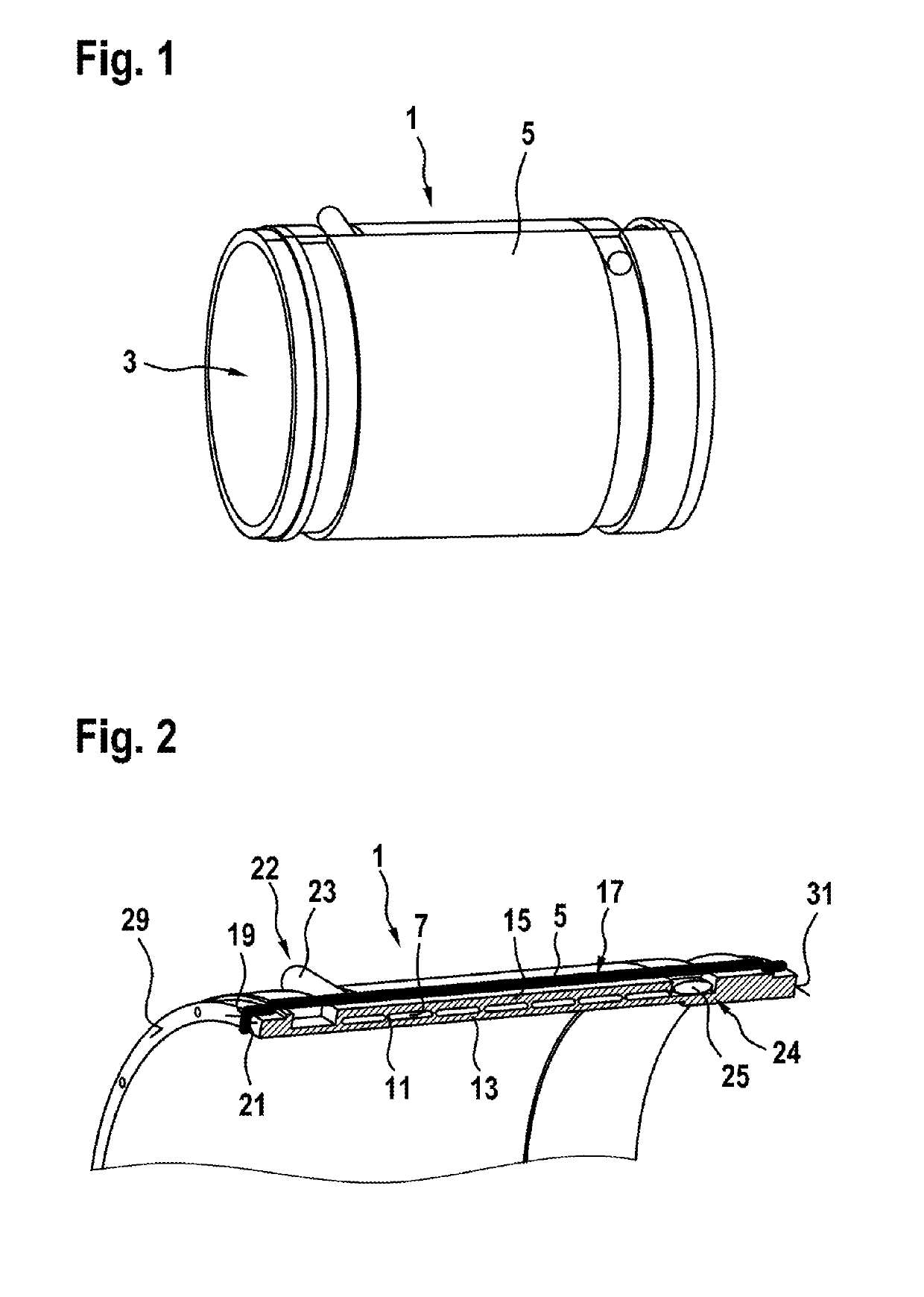
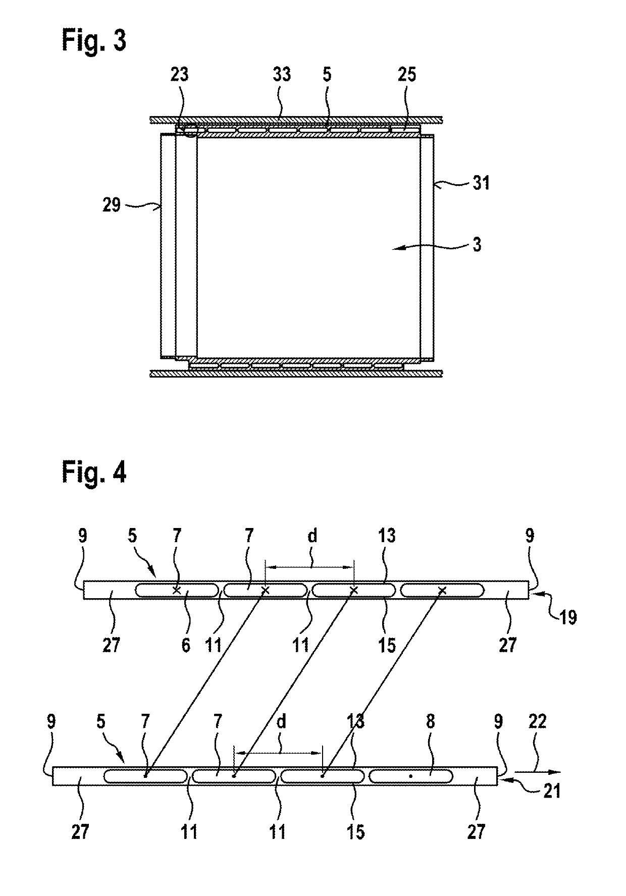
[0028]FIGS. 1, 2 and 3 show a perspective view, a partially cutaway view, and a sectional view of a heat sink 1 according to one embodiment of the invention. The heat sink 1 has a cylindrical shape. A cylinder diameter can be suitably selected in order to enable, for example, a stator of an electric machine (not shown) to be accommodated in an inner chamber 3 of the heat sink 1. The cylinder diameter can be between 2 cm and 100 cm, preferably between 5 cm and 40 cm, for example. An axial length of the heat sink can typically be between 5 cm and 200 cm, preferably between 10 cm and 50 cm.

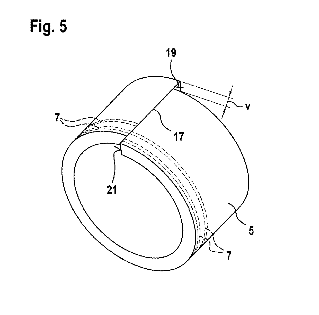
[0029]The heat sink 1 can be formed with the aid of a plate 5; a sectional view of two abutting surfaces 19, 21 of said plate, which are located on end faces positioned opposite each other, is shown in FIG. 4. The plate 5 can be initially flat. Said plate can have a thickness, for example, between 0.5 cm and 20 cm, preferably between 1 cm and 5 cm. The plate 5 can consist of a thermally highly conduc...


PUM


Abstract

The invention relates to a heat sink (1) for an electric machine, which heat sink has at least one cooling channel (7), which adjoins an interior (3) surrounded by the heat sink (1). The heat sink (1) is characterized in that the heat sink (1) is designed as a single-piece plate (5) bent into a closed ring, in the case of which plate two opposite abutting surfaces (19, 21) are connected to each other in a fluid-tight manner in the region of a joint (17), wherein a plurality of closed channels (7) extend in the plate (5), which channels extend at an angle to the circumferential direction of the ring in such a way that adjacent channels (7) lead into each other in the region of the joint (17) and thus form a continuous, spiral channel, which extends in a plurality of spiral turns from an axially front end (22) to an axially rear end (24) of the annular heat sink (1). In particular, the plate (5) of the heat sink (1) can be economically extruded and then brought into a shape suitable for the heat sink (1) by means of bending and axial offsetting. The heat sink (1) can be produced in a simple and economical manner and enables efficient cooling of an electric machine while requiring a minimal installation space.

Description

BACKGROUND OF THE INVENTION[0001]The invention relates to a heat sink for an electric machine and to an electric machine equipped with such a heat sink. The invention further relates to a method for producing the heat sink.[0002]Electric machines of the type used, for example, as electric motors or generators in electric or hybrid vehicles are expected to provide increasingly greater power and power densities. Heat is generated in electric machines as a result of losses occurring during a conversion between electrical energy and mechanical energy, and as a result of other effects. Fluid cooling, in particular liquid cooling, is frequently utilized in order to prevent overheating of the electric machine.[0003]Fluid cooling systems in this case are often formed with the aid of specially designed, for example, double-walled housings, in which a cooling fluid is conveyed through channels or ribs. In this case, the housing adjoins components of the electric machine such as, for example, ...

Claims


Application Information

Patent Timeline
Patent Type & Authority Patents(United States)
IPC IPC(8): H02K5/20H02K9/19
CPCH02K5/20H02K9/19H02K5/203
Inventor PLOEGER, ARMINREICHERT, BIRGITSTEIN, SEBASTIANKNAPPENBERGER, UWELANGE, FABIANCARRILLO, CAMILOROEPKE, MATTHIASKIRCHHOFF, KARSTENBRUNS, SEBASTIAN
Owner ROBERT BOSCH GMBH
Why Eureka
Try Eureka