
Heat exchanger produced from laminar elements

a technology of laminar elements and heat exchangers, which is applied in the direction of laminated elements, mounting, lighting and heating apparatus, etc., can solve the problem of not being able to assume complex three-dimensional shapes, and achieve the effect of high scalabl

Inactive Publication Date: 2013-03-07
VACUUM PROCESS ENG
View PDF7 Cites 2 Cited by
  • Summary
  • Abstract
  • Description
  • Claims
  • Application Information

AI Technical Summary

Benefits of technology

The invention is a heat exchanging device that can be easily and economically produced, and it is highly scalable, allowing for the creation of heat exchangers of any size. Additionally, the device has enhanced surface area features that improve heat exchange efficiency.

Problems solved by technology

These devices, however, are configured in the same manner as the traditional stacked plate configurations, and accordingly cannot assume complex three dimensional shapes.

Method used


Image

  • Heat exchanger produced from laminar elements
  • Heat exchanger produced from laminar elements
  • Heat exchanger produced from laminar elements

Examples


Embodiment Construction

[0047]While the present invention is susceptible of embodiment in various forms, there is shown in the drawings and will hereinafter be described a presently preferred, albeit not limiting, embodiment with the understanding that the present disclosure is to be considered an exemplification of the present invention and is not intended to limit the invention to the specific embodiments illustrated.

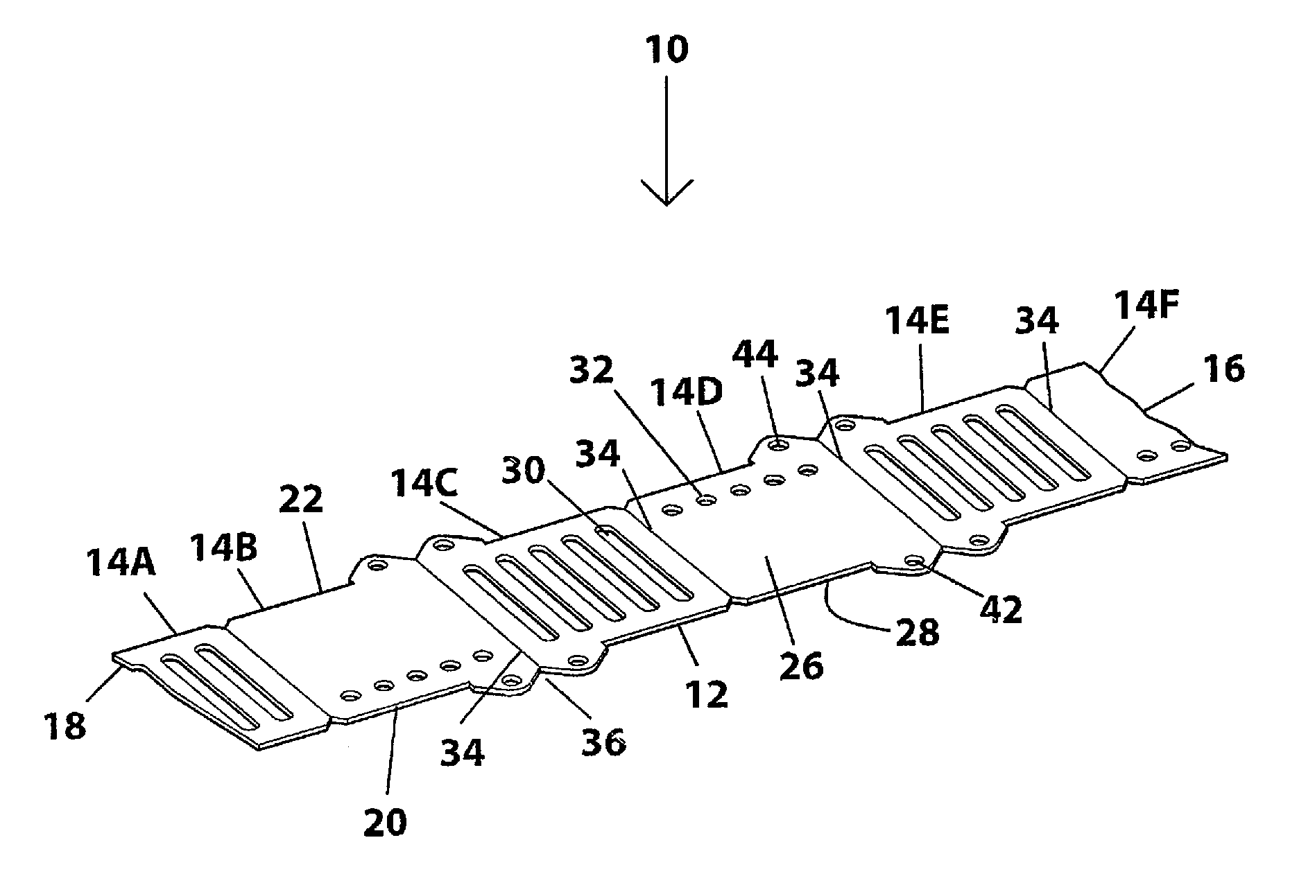
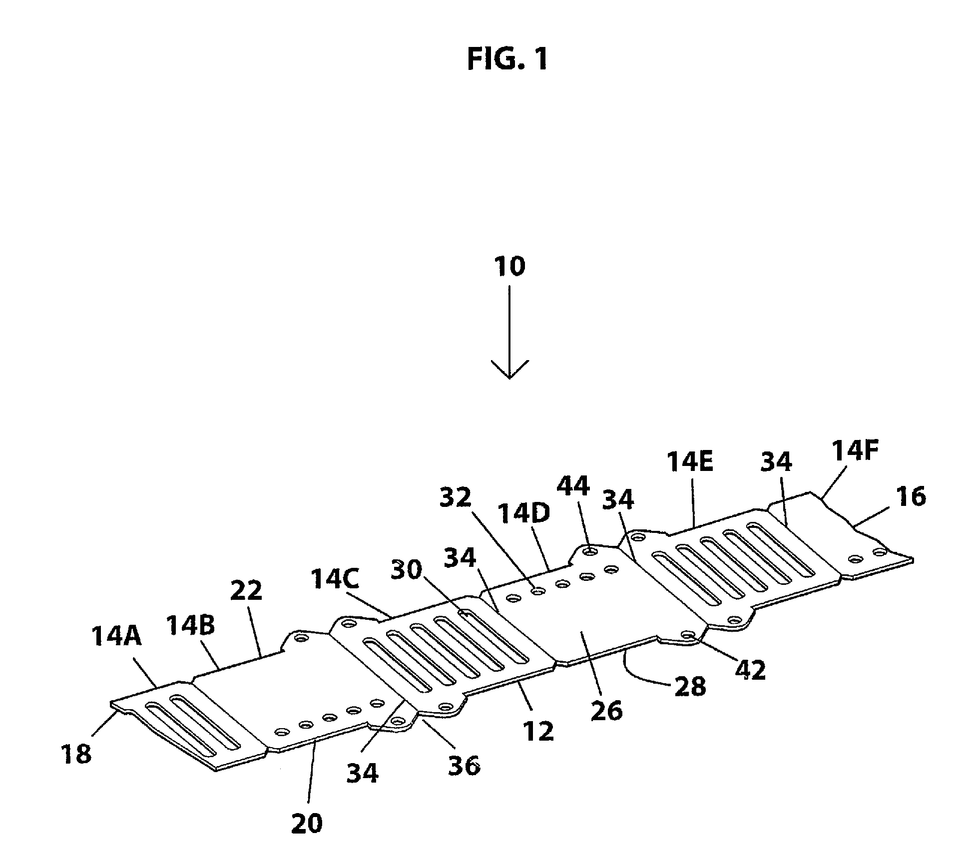
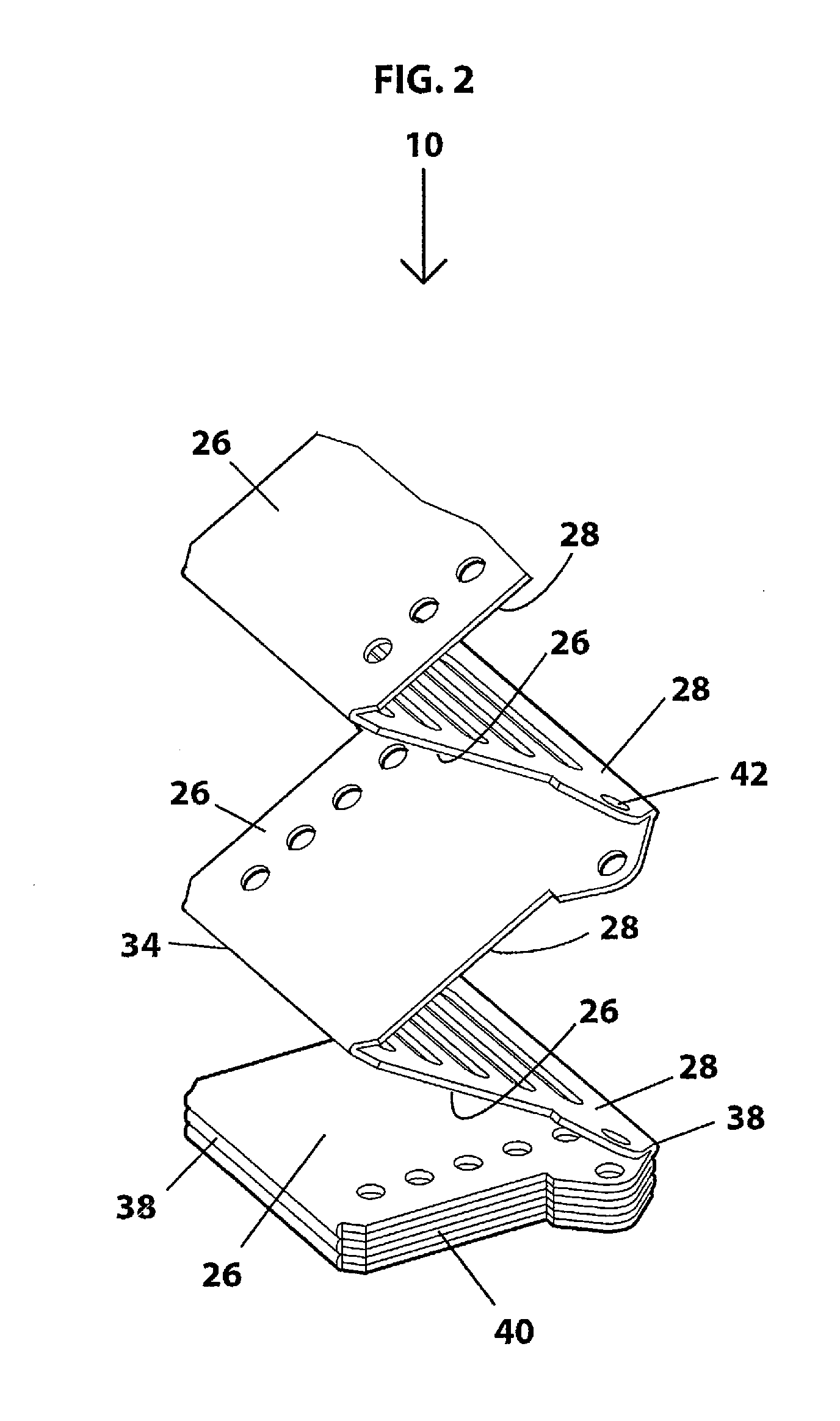
[0048]Referring to FIG. 1, a perspective view of an illustrative embodiment of a heat exchanging device, referred to generally as 10, is illustrated. The heat exchanging device 10 contains a main body 12, preferably made of a laminar material and / or other materials that exchange heat such as aluminum or copper, comprising individual subunit elements 14A, 14B, 14C, 14D, 14E, and 14F, collectively 14. While the illustrative embodiment is shown having 6 subunit elements, the heat exchanging device may have fewer or greater than six. The number of subunits which make up the heat exchanging devic...


PUM


Abstract

The present invention provides a heat exchanging device formable into a three dimensional configuration. The heat exchanger device may be of the heat sink type, a dual fluid type, or virtually any other as may be desired. The heat exchanger device comprises a main body which is formable into a three dimensional shape and has a plurality of individual subunit elements adapted to form a plurality of stacked heat exchanging units. The individual subunits have surface configurations which are adapted to allow fluid flow.

Description

FIELD OF THE INVENTION[0001]This invention is directed toward the field of heat exchangers, and more particularly to a heat exchanging device which can form complex, three dimensional geometrical configurations.BACKGROUND OF THE INVENTION[0002]Often, an operating machine or electronic component or an industrial process system generates waste heat in the course of its normal operation. If this waste heat is not removed, degraded performance or damage to the system may result. Frequently, the operating temperature of a system needs to be precisely maintained in order to obtain optimal performance. For example, it is often desirable to cool the sensors used in thermal imaging cameras to improve the sensitivity of the imager. Further, analytical instruments may require that the sample to be analyzed be presented to the instrument at a precisely controlled temperature.[0003]Heat exchangers permit heat to be removed or added to the sample as may be desired. A common type of heat exchanger...

Claims


Application Information

Patent Timeline
Patent Type & Authority Applications(United States)
IPC IPC(8): F28F7/00
CPCF28F3/086F28F2280/04F28D9/0025
Inventor SCHALANSKY, CARL
Owner VACUUM PROCESS ENG
Learn More