Drilling tool for holemaking in metallic workpieces

Active Publication Date: 2007-07-10
SANDVIK INTELLECTUAL PROPERTY AB
View PDF25 Cites 18 Cited by
  • Summary
  • Abstract
  • Description
  • Claims
  • Application Information

AI Technical Summary

Benefits of technology

[0004]One object of the invention is to eliminate the above mentioned problems of previously known drills and create a drill with improved centering ability. Thus, a primary object of the present invention is to confer to the head of the drill such a geometry that it becomes self-centering at the placing against and the initial penetration of the drill into a workpiece. The drill shall also maintain a good centering ability during the continuing penetration of the workpiece whereby the good centering ability shall be possible to achieve without the necessity of large feeding or placing forces.
[0005]Another object of the present invention is to attain a good centering ability without the necessity of substantially reducing the active cutting edge length. It is another object of the invention to achieve a drill which enables an increased feed and larger drilling speed. Yet another object of the invention is to provide a drill with improved chip evacuating ability during machining and simultaneously attain more stable drilling and improved tightness of tolerances. It is another object of the invention to provide a drill having such geometry in the proximity of the drill center that regrinding of the cutting edge portions can occur in a better way than heretofor.

Problems solved by technology

With these prior art drills, however, clearance surfaces at the edges extend in an unbroken manner from the peripheral end of the edge until its curved portion adjacent the core centering portion.

Method used


Image

  • Drilling tool for holemaking in metallic workpieces
  • Drilling tool for holemaking in metallic workpieces
  • Drilling tool for holemaking in metallic workpieces

Examples


Embodiment Construction

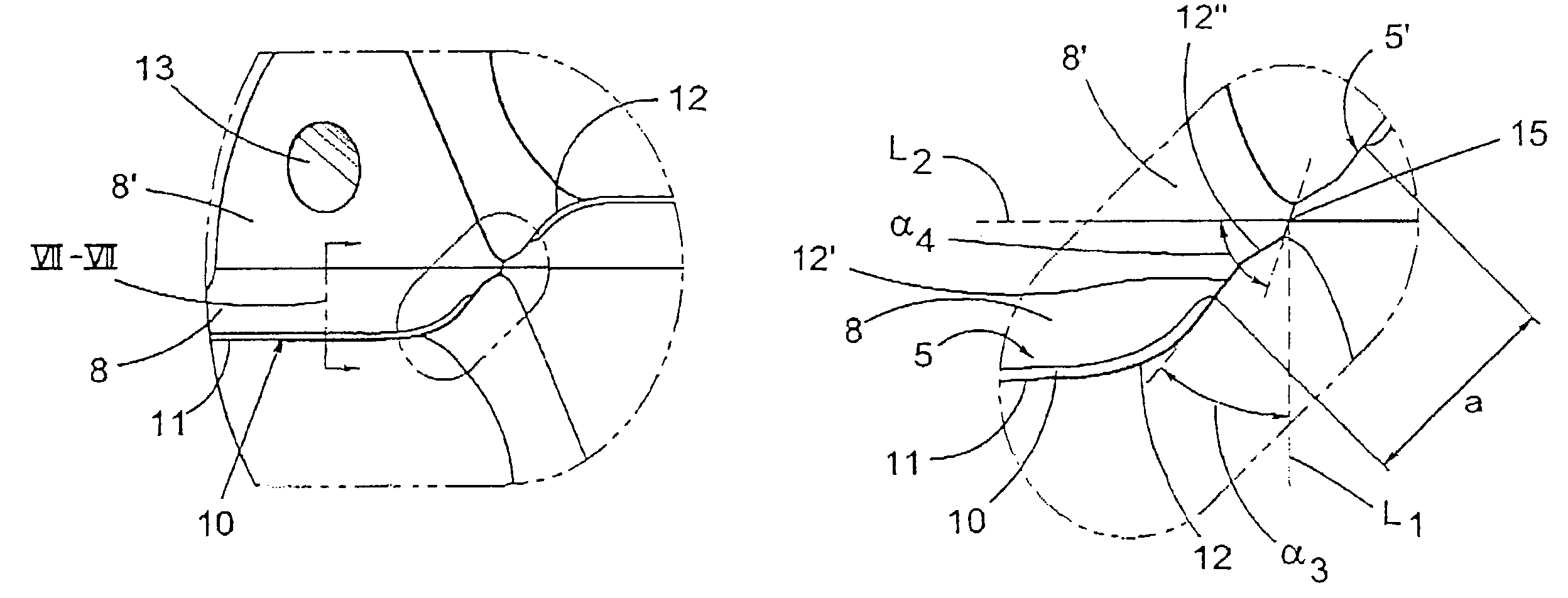
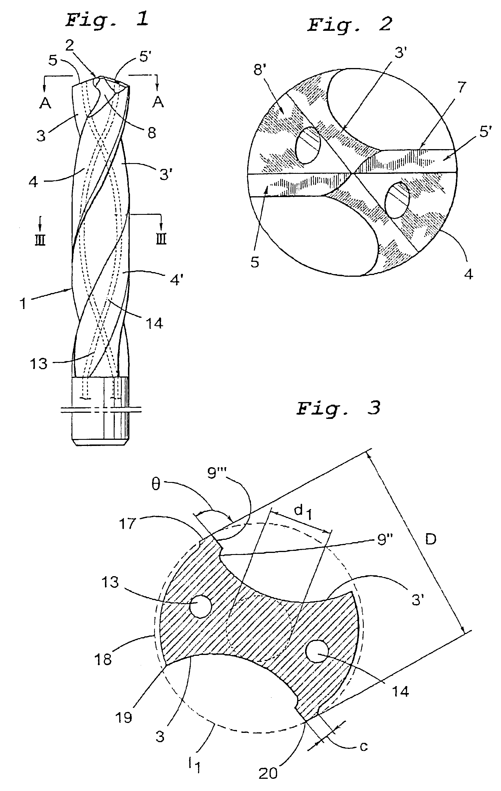
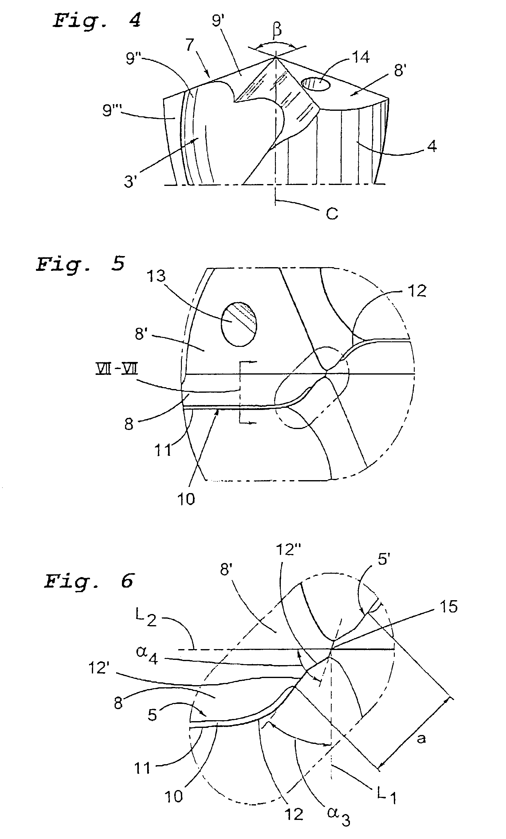
[0018]The drill shown in FIGS. 1 and 2 comprises a shaft 1 and a drill head designated in its entirety by 2. Two helical or screw-formed flutes 3,3′ are formed in the shaft 1, which flutes are delimited by analogous, helically formed protruding lands 4,4′. The drill head 2 comprises two, in the present case identical, but inverted cutting elements 5,5′ which extend in each other's extension in a common main plane A—A that cuts the center or rotation axis of the drill (in FIG. 4, this axis is designated by C). In this embodiment, the cutting elements 5,5′ are made as parts of a common cutting body, e.g. of cemented carbide, which is an integrated portion of the shaft made in same material and thereafter ground to its final shape, as shown in the drawings. This final shaping of the drilling tool can occur by grinding, injection molding, or by other means.

[0019]Each individual cutting element 5,5′ comprises a cutting edge designated in its entirety by 7, which is generally delimited be...


PUM

PropertyMeasurementUnit
Fractionaaaaaaaaaa
Fractionaaaaaaaaaa
Angleaaaaaaaaaa

Abstract

A drill comprises a shaft with chip conveying flutes and a drill head at its forward end with at least two cutting inserts. Each cutting insert is provided with at least one cutting edge which is delimited between a chipbreaking surface and first relief surface and which includes an outer straight edge. In the proximity of the center axis of the shaft, a curved cutting edge section is provided, to which there is connected an adjacent enforcement bevel. The cutting edge is in direct proximity to a center axis, and is terminated by a chisel edge between the cutting inserts to serve as a centering core portion. The curved cutting edge section is inwardly followed by a primary straight portion without an adjacent enforcement bevel in a direction that is oriented at an angle of between approximately 40–50° in relation to a horizontal line that extends through the center axis of the drill.

Description

[0001]This application claims priority under 35 U.S.C. §119 to Patent Application Serial No. 0201517-0 filed in Sweden on May 17, 2002, the entire content of which is hereby incorporated by reference.FIELD OF THE INVENTION[0002]The present invention relates to a drill for machining of metal workpieces. More particularly, the present invention relates to a drill for machining of metal workpieces comprising a shaft with chip conveying flutes and an integral drill head at the front of the shaft, with two or more cutting inserts, each of which comprise at least one cutting edge and a relief surface and which at least in the vicinity of the geometric center or rotation axis of the drill comprises a curved section.BACKGROUND OF THE INVENTION[0003]Drills of the above-noted type are previously known from U.S. Pat. No. 4,983,079 and U.S. Pat. No. 5,088,863. With these prior art drills, however, clearance surfaces at the edges extend in an unbroken manner from the peripheral end of the edge u...

Claims


Application Information

Patent Timeline
IPC IPC(8): B23B51/02B23B51/00B23B51/06
CPCB23B51/02B23B51/06Y10T408/78B23B2251/14Y10T408/9097B23B2251/04
Inventor FRISENDAHL, JORGEN
Owner SANDVIK INTELLECTUAL PROPERTY AB
Why Eureka
Try Eureka