Drilling tool for holemaking in metallic workpieces

A technology of central axis, cutting edge, applied in the field of drilling for metal workpiece processing

Inactive Publication Date: 2007-10-10
SANDVIK INTELLECTUAL PROPERTY AB
View PDF6 Cites 0 Cited by
  • Summary
  • Abstract
  • Description
  • Claims
  • Application Information

AI Technical Summary

Problems solved by technology

Although a centering portion is provided, the centering capability of such drills is only slightly improved compared to conventional drills without such a centering portion

Method used


Image

  • Drilling tool for holemaking in metallic workpieces
  • Drilling tool for holemaking in metallic workpieces
  • Drilling tool for holemaking in metallic workpieces

Examples


Embodiment Construction

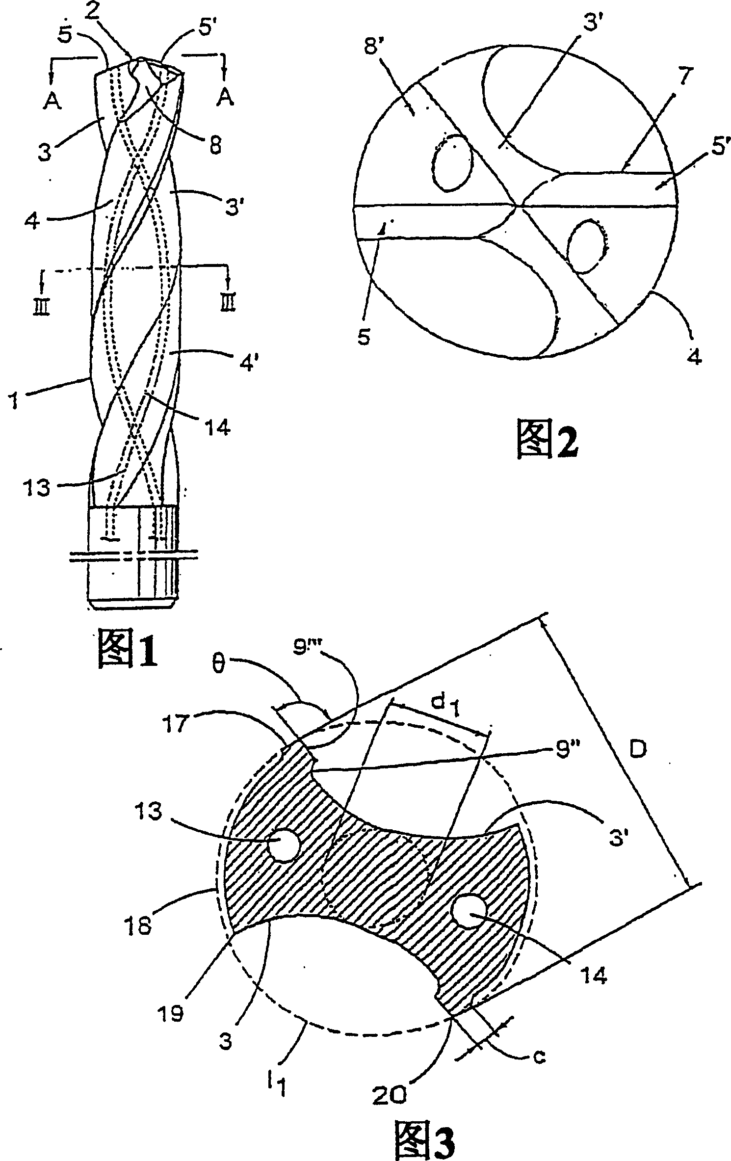
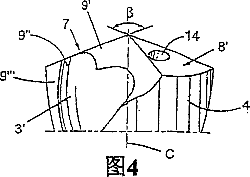
[0018] The drill shown in FIGS. 1 and 2 comprises a shaft 1 and a drill head, the whole of which is indicated at 2 . Two helical or thread-shaped grooves 3, 3' are formed on the shaft 1, which grooves are delimited by similar helically protruding lands 4, 4'. The head 2 of the drill comprises two, in the present case identical, but mutually opposite cutting elements 5, 5', which extend in the extension of each other in a common main plane A-A, which cuts the center of the drill Or the axis of rotation (in Figure 4, this axis is denoted by C). In this embodiment, the cutting element 5, 5' is manufactured as a common cutting body part, such as cemented carbide, which is an integral part of the shaft made of the same material, and then ground to its final shape, As shown in the attached picture. The final shape of the drilling tool can be produced by grinding, injection molding or other means.

[0019] Each individual cutting element 5, 5' comprises a cutting edge, indicated g...


PUM


Abstract

A drill comprises a shaft with chip conveying flutes and a drill head at its forward end with at least two cutting inserts. Each cutting insert is provided with at least one cutting edge which is delimited between a chipbreaking surface and first relief surface and which includes an outer straight edge. In the proximity of the center axis of the shaft, a curved cutting edge section is provided, to which there is connected an adjacent enforcement bevel. The cutting edge is in direct proximity to a center axis, and is terminated by a chisel edge between the cutting inserts to serve as a centering core portion. The curved cutting edge section is inwardly followed by a primary straight portion without an adjacent enforcement bevel in a direction that is oriented at an angle of between approximately 40-50 DEG in relation to a horizontal line that extends through the center axis of the drill.

Description

[0001] This application claims priority under 35 U.S.C. §119 to Patent Application No. 0201517-0 filed May 17, 2002 in Sweden, the entire contents of which are hereby incorporated by reference. technical field [0002] The invention relates to drills for machining metal workpieces. More specifically, the present invention relates to a drill for machining metal workpieces comprising a shaft with chip conveying grooves and an integral drill head at the front of the shaft with two or more cutting inserts, each including at least one cutting edge and a relief surface, and which includes a curved portion at least near the geometric center of the drill or the axis of rotation. Background technique [0003] Drills of the type mentioned above are already known from US-4,983,079 and US-5,088,863. With these prior art drills, however, the clearance surface at each edge extends in an unbroken manner from the outer edge end of the edge up to its curved portion adjacent the central port...

Claims


Application Information

Patent Timeline
Patent Type & Authority Patents(China)
IPC IPC(8): B23B51/02B23B51/00B23B51/06
CPCB23B2251/14B23B51/02B23B2251/04B23B51/06Y10T408/78Y10T408/9097
Inventor 约尔根·弗里森达尔
Owner SANDVIK INTELLECTUAL PROPERTY AB
Why Eureka
Try Eureka