Heating apparatus, coating and development apparatus, and heating method

一种加热装置、加热方法的技术,应用在照明和加热设备、加热来干燥固体材料、炉子组件等方向,能够解决晶片弯曲程度大、位置偏移等问题,达到降低附着、防止位置偏移的效果

Active Publication Date: 2006-09-27
TOKYO ELECTRON LTD
View PDF1 Cites 9 Cited by
  • Summary
  • Abstract
  • Description
  • Claims
  • Application Information

AI Technical Summary

Problems solved by technology

However, if the wafer is 12 inches or larger, the wafer may be warped to a large extent. Therefore, if the height of the protrusion on the heating plate is 0.1mm, the wafer may come into contact with the heating plate and cause a dislocation. offset

Method used


Image

  • Heating apparatus, coating and development apparatus, and heating method
  • Heating apparatus, coating and development apparatus, and heating method
  • Heating apparatus, coating and development apparatus, and heating method

Examples


Embodiment Construction

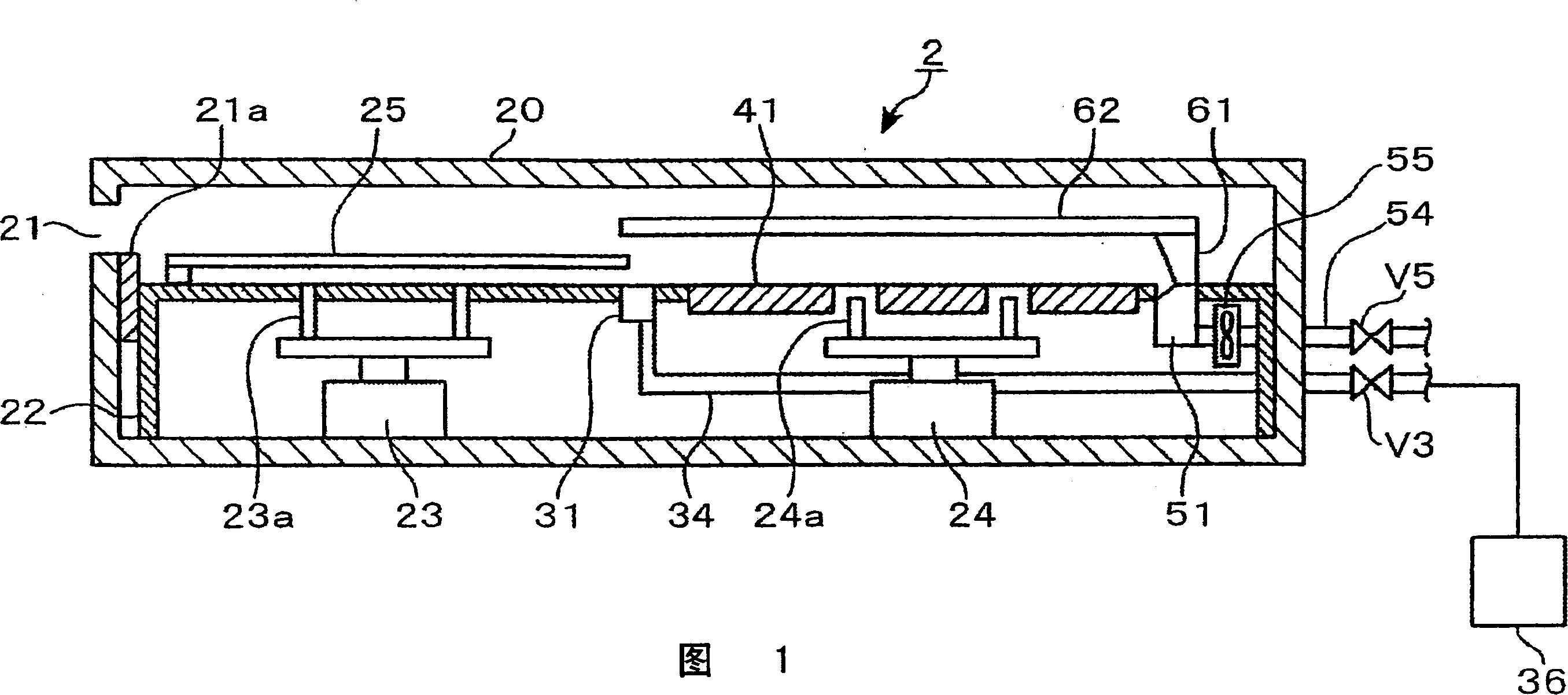
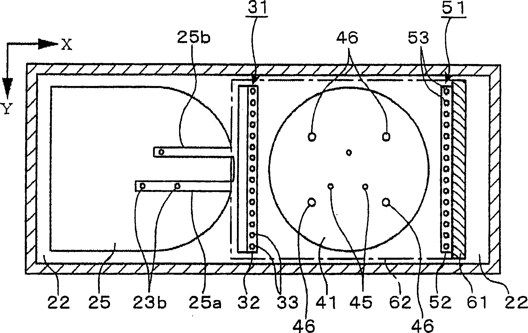
[0034] Hereinafter, as an example of an embodiment of the heating device according to the present invention, for example, a semiconductor wafer (hereinafter simply referred to as a wafer) W, on which a resist solution is applied as a coating solution on the surface, is subjected to heat treatment. The heating device 2 for forming a resist film on the surface of the wafer W will be described with reference to FIGS. 1 to 3 . In addition, as the size of the wafer W, for example, a size of 12 inches or more is used. This heating device 2 has a box body 20, and a transport port 21 for wafers W is opened on a side wall of the box body 20, and the transport port 21 is freely openable and closable by a shutter 21a. The shutter 21a is provided to prevent the airflow formed around the wafer W described later from being disturbed by outside air flowing into the housing 20 through the transfer port 21 when the wafer W is heated. 21, for example, an air curtain is provided in place of the...


PUM


Abstract

A heating apparatus is configured to include a hot plate at which a substrate is placed, a top plate opposed to the substrate, a gas discharging part provided on one end side of the hot plate for discharging gas between the hot plate and the top plate, an exhaust part provided to be opposed to the gas discharging part with the hot plate interposed therebetween, and a heating part independently heating a first region and a second region of the substrate. A heating process is performed with good within-wafer uniformity by forming an unidirectional flow to heat the first region and the second region at different temperatures.

Description

technical field [0001] The present invention relates to a heating device for heat-treating a substrate coated with a coating liquid, a coating and developing device including the heating device, and a heating method. Background technique [0002] As an apparatus for forming resist patterns on semiconductor wafers (hereinafter referred to as wafers) and glass substrates for LCDs (liquid crystal displays), a coating and developing apparatus for applying a resist to a wafer and developing the exposed wafer is used. A heating device called a baking device is incorporated in this device, and it functions to dry the solvent in the resist liquid, for example, in a device that heats a wafer coated with a resist liquid. [0003] As this heating device, generally, as shown in FIG. The central portion of the cover 12 sucks the exhaust gas, and heat treatment is performed while forming an air flow from the outer periphery of the wafer toward the center as indicated by the arrow in the ...

Claims


Application Information

Patent Timeline
Patent Type & Authority Applications(China)
IPC IPC(8): F26B3/06
CPCF27B5/04H01L21/67109F27D3/0084H01L21/324
Inventor 福冈哲夫北野高广松冈伸明
Owner TOKYO ELECTRON LTD
Why Eureka
Try Eureka