Heat exchanger for vehicular air conditioning apparatus

a technology for vehicular air conditioning and heat exchangers, which is applied in the direction of indirect heat exchangers, lighting and heating apparatus, and machine operation modes, etc., can solve the problems of affecting the efficiency of the heat exchanger, etc., and achieves the effect of effectively discharging the air contained

Inactive Publication Date: 2011-01-13
KEIHIN CORP +1
View PDF3 Cites 18 Cited by
  • Summary
  • Abstract
  • Description
  • Claims
  • Application Information

AI Technical Summary

Benefits of technology

[0008]A general object of the present invention is to provide a heat exchanger for use in a vehicular air conditioning apparatus, which is capable of effectively discharging air contained in a medium, to the exterior of the housing and obtaining air having a desired temperature by heat exchange.

Problems solved by technology

Accumulation of the retained air tends to cause noise when the air is stirred with flow of the heat exchange medium, and also tends to hinder a predetermined amount of the head exchange medium from being supplied into the heat exchanger.
As a result, heat exchange performance of the heat exchanger becomes deteriorated, and thus, it is not possible for the heat exchanger to let the air that passes through the heat exchanger to have a desired temperature.

Method used


Image

  • Heat exchanger for vehicular air conditioning apparatus
  • Heat exchanger for vehicular air conditioning apparatus
  • Heat exchanger for vehicular air conditioning apparatus

Examples


Embodiment Construction

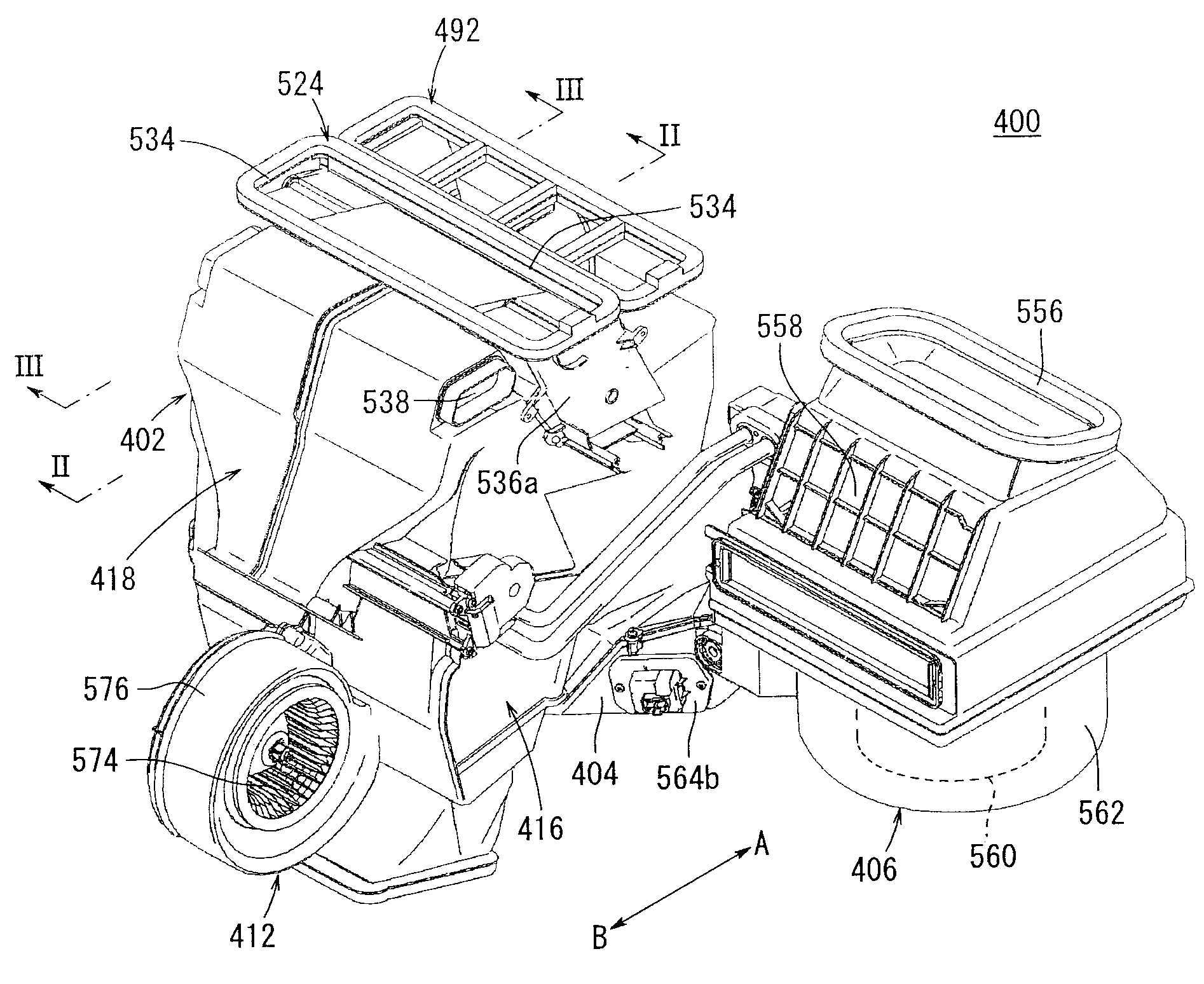
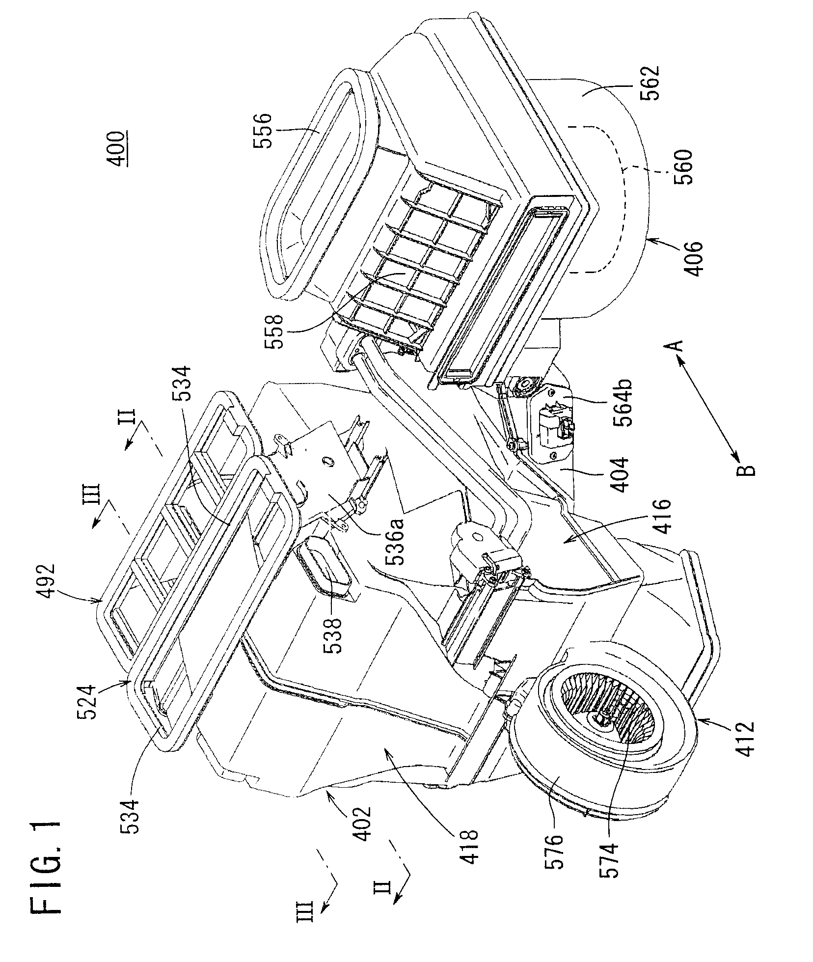
[0047]A preferred embodiment of a heat exchanger for use in a vehicular air conditioning apparatus shall be presented and explained in detail below with reference to the accompanying drawings. In FIG. 1, reference numeral 400 indicates a vehicular air conditioning apparatus using the heat exchanger according to an embodiment of the present invention. The vehicular air conditioning apparatus 400, for example, is installed in a vehicle having three rows of seats arranged along the direction of travel of the vehicle. In the following descriptions, the first row of seats in the vehicle compartment of the vehicle is designated as front seats, the second row of seats is designated as middle seats, and the third row of seats is designated as rear seats.

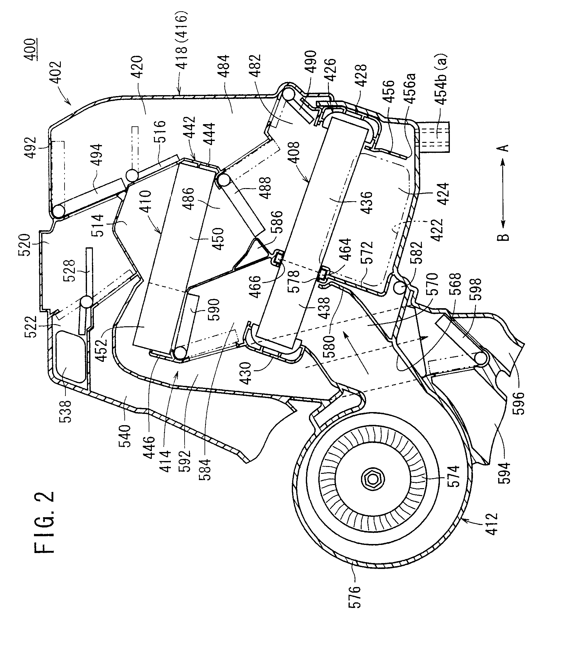
[0048]Further, the vehicular air conditioning apparatus 400 is installed so that the righthand side thereof shown in FIG. 2 (in the direction of arrow A) is oriented toward the front side of the vehicle, whereas the lefthand side (in the dir...


PUM


Abstract

A heater core is inclined at a predetermined angle such that an end thereof on the front side of a vehicle is positioned below the other end thereof. A supply conduit for supplying heated water and a discharge conduit for discharging the heated water having circulated through the heater core are connected to a side surface of the heater core. A baffle plate having a cross-shaped cross-section is disposed inside the heater core and extends along the direction in which the supply and discharge conduits are arranged. Heated water from the supply conduit is supplied into the heater core, flows from the end of the heater core along the upper side of the baffle plate, and thereafter turns round at the other end of the heater core. Then, the heated water flows along the lower side of the baffle plate and is discharged from the discharge conduit.

Description

BACKGROUND OF THE INVENTION[0001]1. Field of the Invention[0002]The present invention relates to a heat exchanger mounted in and for use in a vehicular air conditioning apparatus for adjusting temperature in a vehicle compartment, and for cooling and heating air that is blown into the vehicle compartment.[0003]2. Description of the Related Art[0004]In a vehicular air conditioning apparatus that is mounted in a vehicle, internal and external air is introduced into a casing by a blower, and after cooled air, which has been cooled by an evaporator that forms a cooling means, and heated air, which has been heated by a heater core that forms a heating means, are mixed together in the casing at a predetermined mixing ratio, the mixed air is blown out from a defroster blow-out port, a face blow-out port, or a foot blow-out port, whereby adjustment of temperature and humidity in the vehicle compartment is carried out.[0005]With this type of vehicular air conditioning apparatus, for example,...

Claims


Application Information

Patent Timeline
Patent Type & Authority Applications(United States)
IPC IPC(8): B60H1/00
CPCB60H1/00064B60H2001/00099B60H2001/00135F28D1/05366F28F9/22F28D2021/0096F28F9/002F28F9/0204F28D2021/0085
Inventor SETO, TAKAHIROKITAMURA, TSUNETOSHIKANEMARU, JUNICHIKAKIZAKI, SHINJI
Owner KEIHIN CORP
Why Eureka
Try Eureka