

Cylindrical secondary battery of improved safety
a technology of cylindrical secondary batteries and safety, applied in secondary cell servicing/maintenance, cell components, wound/folded electrode electrodes, etc., can solve the problems of low stability of lithium secondary batteries, inability to achieve desired safety operation process, and inability to discharge high-pressure gas effectively. , the effect of improving battery safety
Active Publication Date: 2012-05-10
LG ENERGY SOLUTION LTD
View PDF5 Cites 39 Cited by
- Summary
- Abstract
- Description
- Claims
- Application Information
AI Technical Summary
Benefits of technology
The present invention relates to a cylindrical secondary battery with an electrode assembly mounted in a cylindrical can. The battery has a current interruptive device and a safety vent to prevent overcharging and internal pressure buildup that can lead to battery explosion. The safety vent has a notched portion to allow gas to escape. The battery also includes a cap assembly with a current interruptive device and a gasket for the current interruptive device. The technical effects of the invention include improved safety and stability of the battery, as well as increased energy density and efficiency of the battery.
Problems solved by technology
Meanwhile, lithium secondary batteries have a disadvantage of low stability.
Eventually, combustion and explosion of battery may occur.
For example, although a great amount of gas is generated, in the case where the gas is not efficiently transported to the safety vent, the desired safety operation process cannot proceed.
Furthermore, unless a great deal of gas is generated within a short period of time, and the gas reaches the safety vent and induces a predetermined operation process, the internal pressure of battery rapidly increases, inducing explosion.
When heat generated from the batteries rapidly increases within a short period of time, thermal runaway may occur.
As the phenomenon further accelerates, the risk, that the battery may be combusted or exploded, considerably increases, thus disadvantageously causing a serious safety problem.
Method used
View moreImage
Smart ImageViewing Examples

Examples
example 2
[0117]A battery was fabricated in the same manner as in Example 1 except that the thickness of the first notch was 0.1 mm and the thickness of the second notch was 0.06 mm in the process of manufacturing the safety vent.
example 3
[0118]A battery was fabricated in the same manner as in Example 1 except that the thickness of the first notch was 7 mm and the thickness of the second notch was 0.06 mm in the process of manufacturing the safety vent.
example 4
[0119]A battery was fabricated in the same manner as in Example 1 except that fluoroethylene carbonate was contained in an amount of 20% by weight, based the total weight of the electrolyte in the process of preparing the electrolyte.
Login to View More PUM
| Property | Measurement | Unit |
|---|---|---|
| angle | aaaaa | aaaaa |
| temperature | aaaaa | aaaaa |
| angle | aaaaa | aaaaa |
Abstract
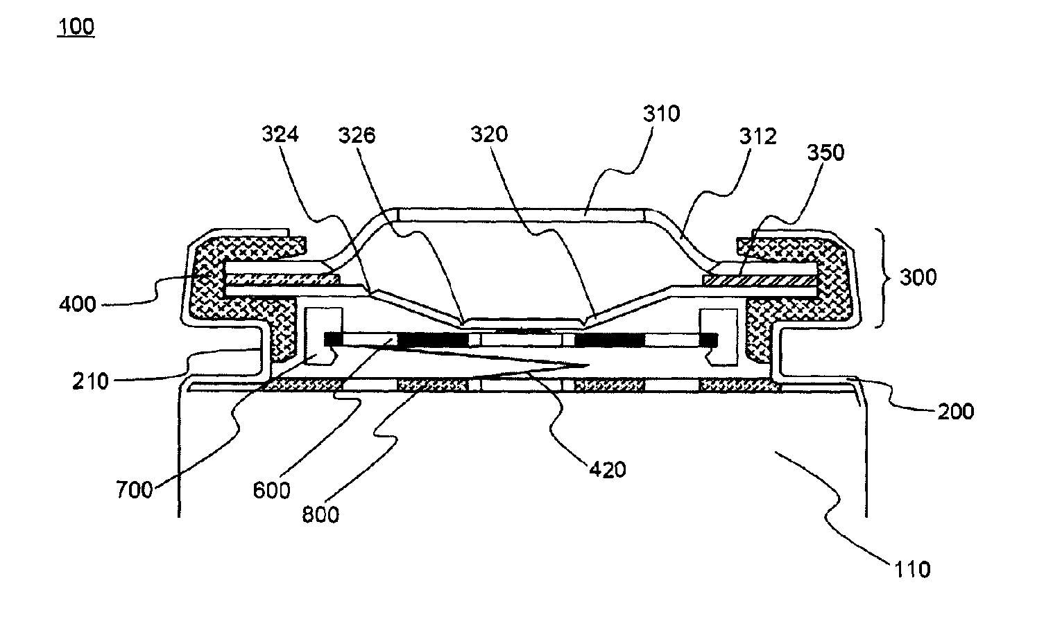
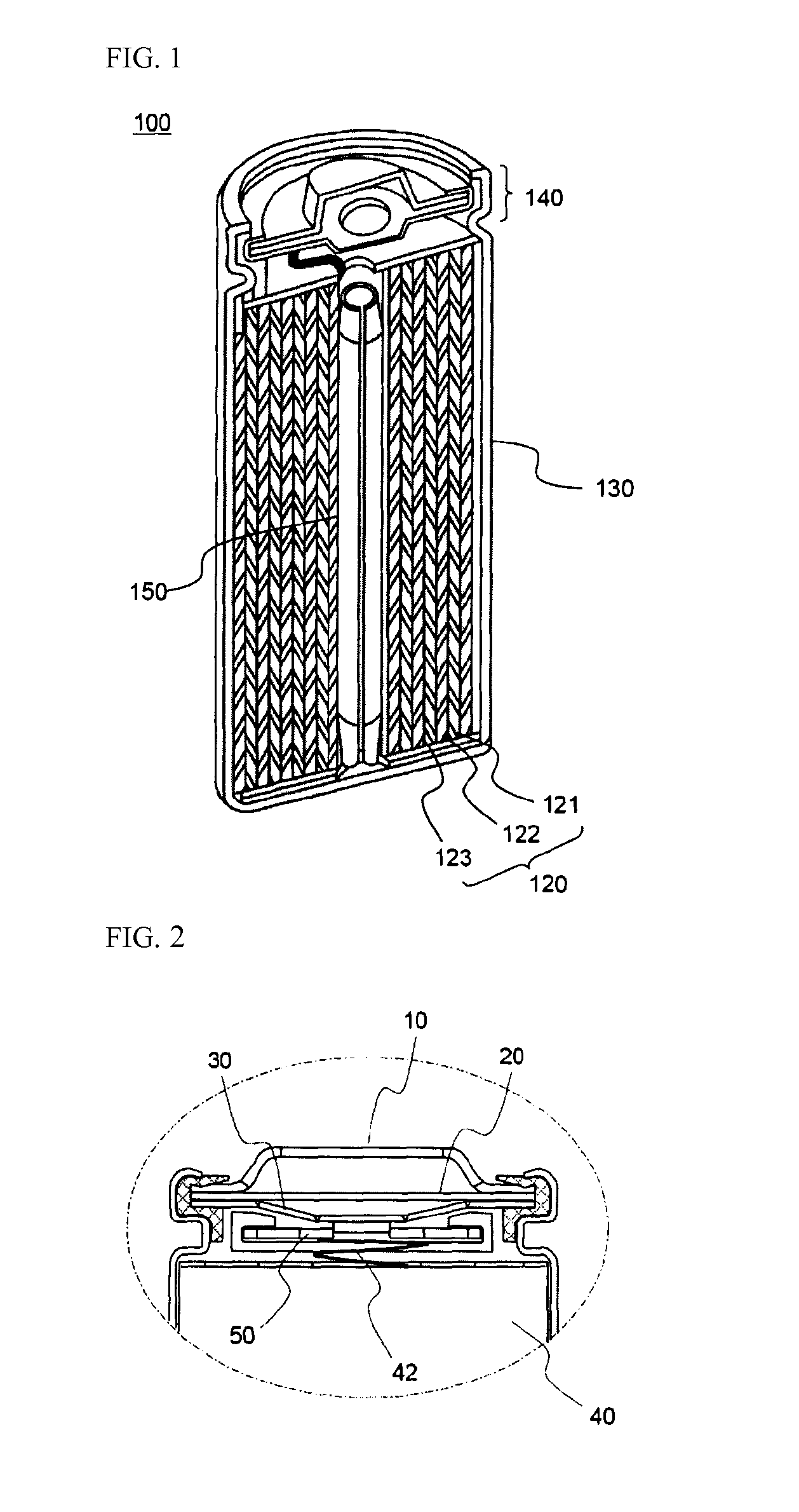
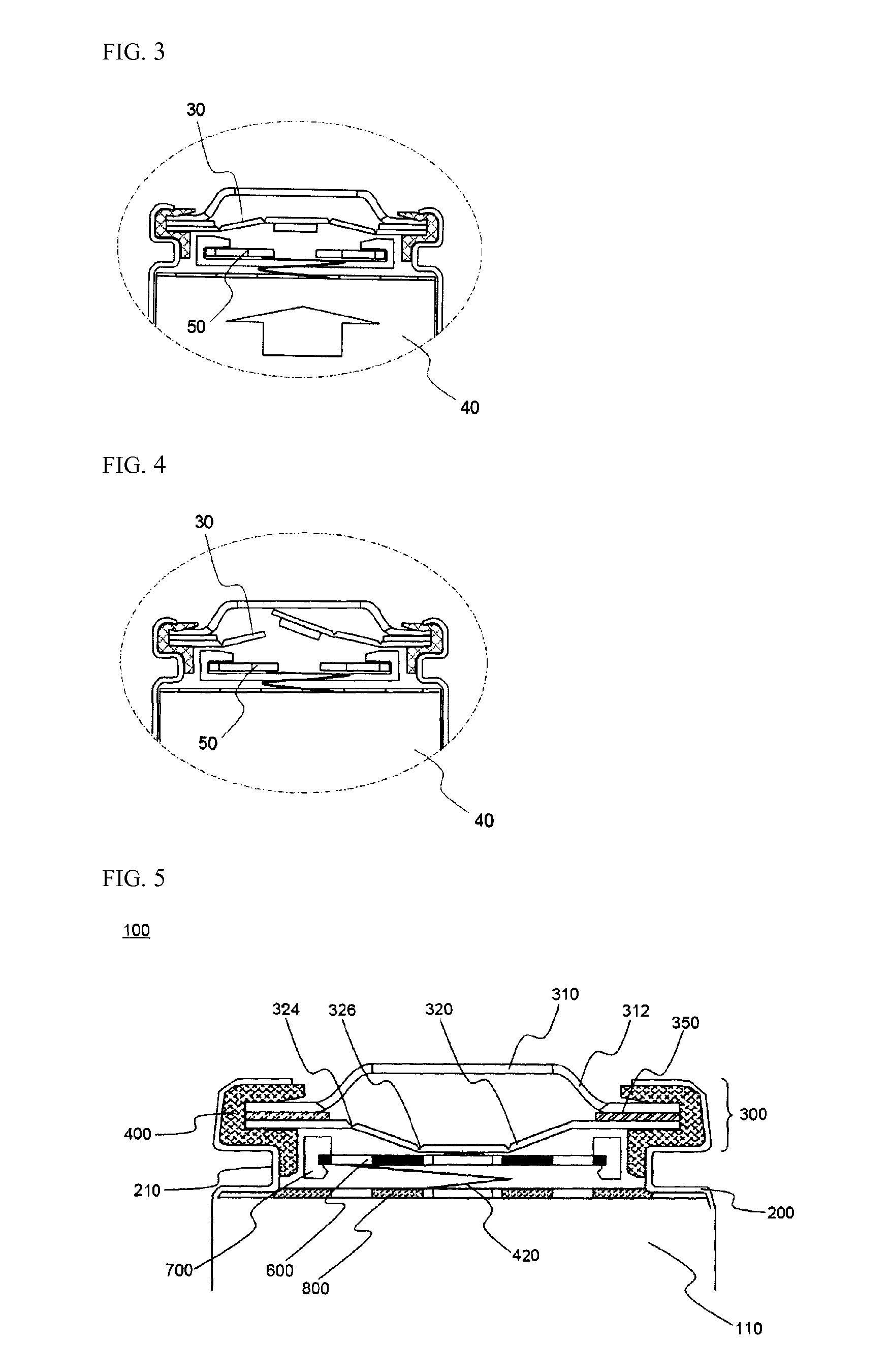
Provided is a cylindrical battery in which an electrode assembly fabricated by rolling a cathode / separator / anode and an electrolyte are provided in a cylindrical can, wherein a cap assembly mounted on the opening top of the cylindrical can comprises: a safety vent provided with a predetermined notch, to allow breakage due to high-pressure gas of the battery, a current interruptive device to interrupt current, welded to the bottom of the safety vent, and a gasket for the current interruptive device to surround the periphery of the current interruptive device, wherein the current interruptive device comprises two or more through holes to allow exhaustion of gas, wherein the through holes have a size of 20 to 50% with respect to the total area of the current interruptive device.
Description
TECHNICAL FIELD[0001]The present invention relates to a cylindrical secondary battery. More specifically, the present invention relates to cylindrical battery in which an electrode assembly fabricated by rolling a cathode / separator / anode and an electrolyte are provided in a cylindrical can, wherein a cap assembly mounted on the opening top of the cylindrical can comprises: a safety vent provided with a predetermined notch, to allow breakage due to high-pressure gas of the battery, a current interruptive device to interrupt current, welded to the bottom of the safety vent, and a gasket for the current interruptive device to surround the periphery of the current interruptive device, wherein the current interruptive device comprises two or more through holes to allow exhaustion of gas, wherein the through holes have a size of 20 to 50% with respect to the total area of the current interruptive device.BACKGROUND ART[0002]Technological development and increased demand for mobile equipmen...
Claims
Login to View More Application Information
Patent Timeline
 Patent Type & AuthorityApplications(United States)
IPC IPC(8): H01M10/42H01M2/20H01M2/12
CPCH01M2/1241H01M10/0431H01M2/345H01M50/3425H01M50/578Y02E60/10Y02P70/50H01M10/0525H01M10/0587
InventorKIM, JI YOUNGKIM, JUNGJINLEE, KWAN SOOKIM, SUNGJONGKIM, SOORYOUNGKU, CHAHUNRYU, DUKHYUNJUNG, BYUNG KYU
OwnerLG ENERGY SOLUTION LTD