System and method for power-efficient charging and discharging of a capacitive load from a single source

a capacitive load and charging system technology, applied in the field of electronic circuits and systems, can solve the problems of limiting battery life, high cost, and low efficiency

Inactive Publication Date: 2002-02-19
UNIV OF SOUTHERN CALIFORNIA
View PDF66 Cites 42 Cited by
  • Summary
  • Abstract
  • Description
  • Claims
  • Application Information

AI Technical Summary

Problems solved by technology

That is, low efficiency leads to higher costs due to the waste of energy and the need for larger power supplies.
For battery powered systems, power dissipation limits battery life.
This necessitates larger batteries which increases the cost and weight of the system while limiting the applicability thereof.
As an example, consider coronary pacemakers where power dissipation is a critical concern due to the difficultly of accessing the battery for replacement and the cost and inconvenience associated with the use of larger batteries.
Accordingly, systems which exhibit considerable power dissipation often require measures such as heat sinks to protect or cool system components from the heat created by the circuit.
The use of heat sinks and the like adds to the cost, size and weight of the system and thereby limits the utility of same.
However, in addition to costly interfacing issues, attempts to lower the voltage of digital processors and the like have been limited by the fact that the trend is to higher processing speeds which cannot be attained at arbitrarily low operating voltages.

Method used


Image

  • System and method for power-efficient charging and discharging of a capacitive load from a single source
  • System and method for power-efficient charging and discharging of a capacitive load from a single source
  • System and method for power-efficient charging and discharging of a capacitive load from a single source

Examples


Embodiment Construction

Illustrative embodiments and exemplary applications will now be described with reference to the accompanying drawings to disclose the advantageous teachings of the present invention.

While the present invention is described herein with reference to illustrative embodiments for particular applications, it should be understood that the invention is not limited thereto. Those having ordinary skill in the art and access to the teachings provided herein will recognize additional modifications, applications, and embodiments within the scope thereof.

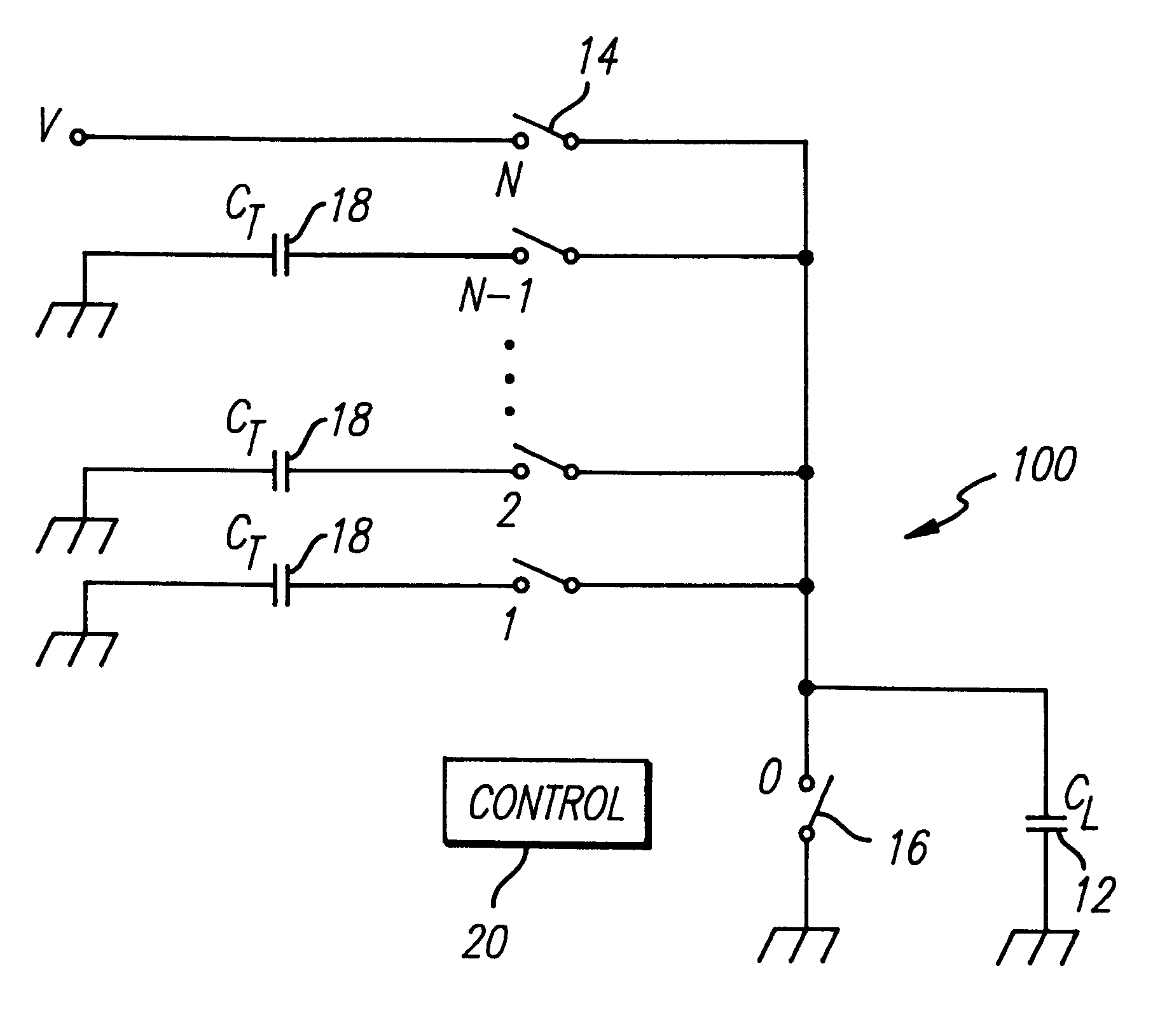
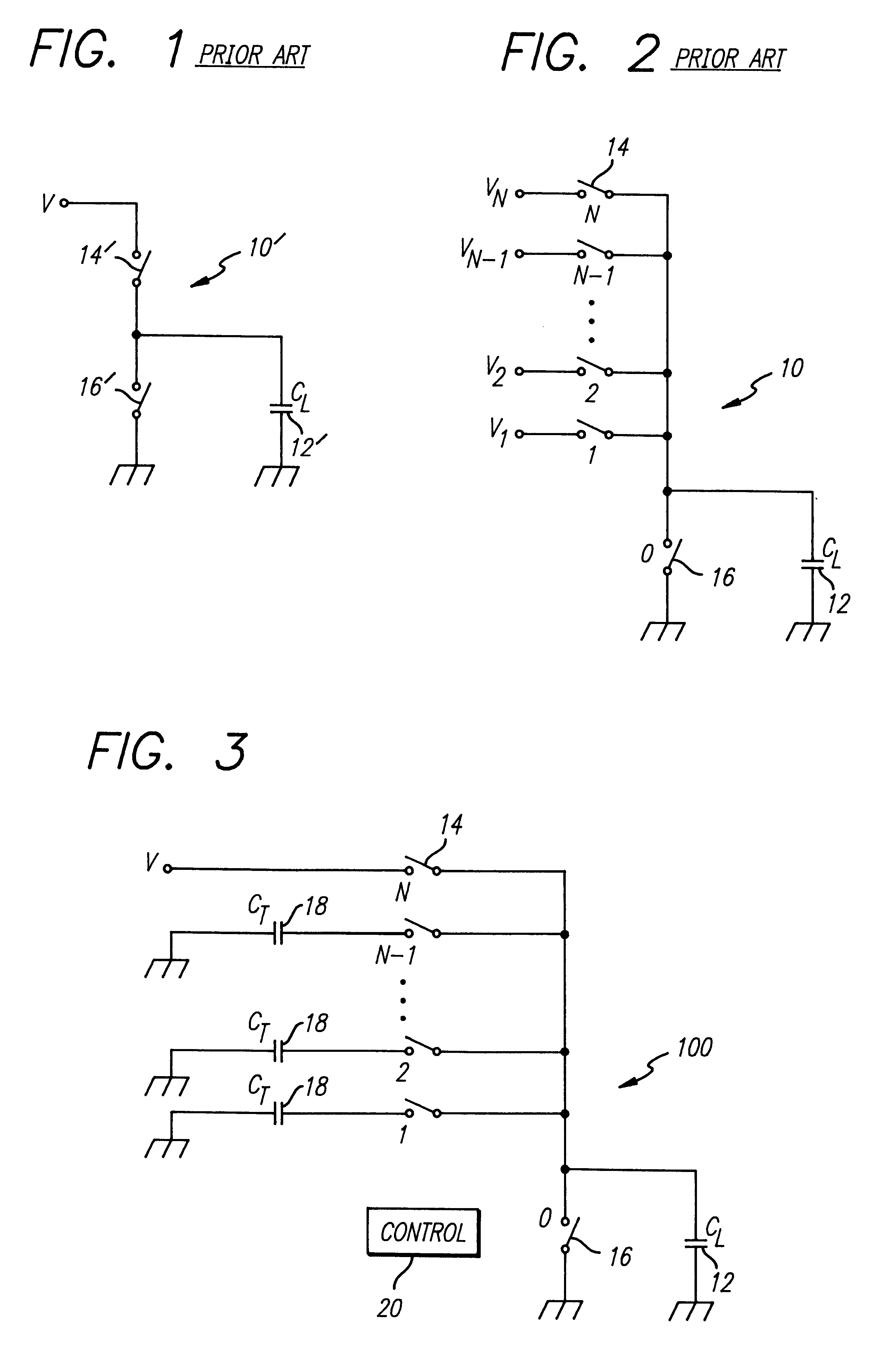
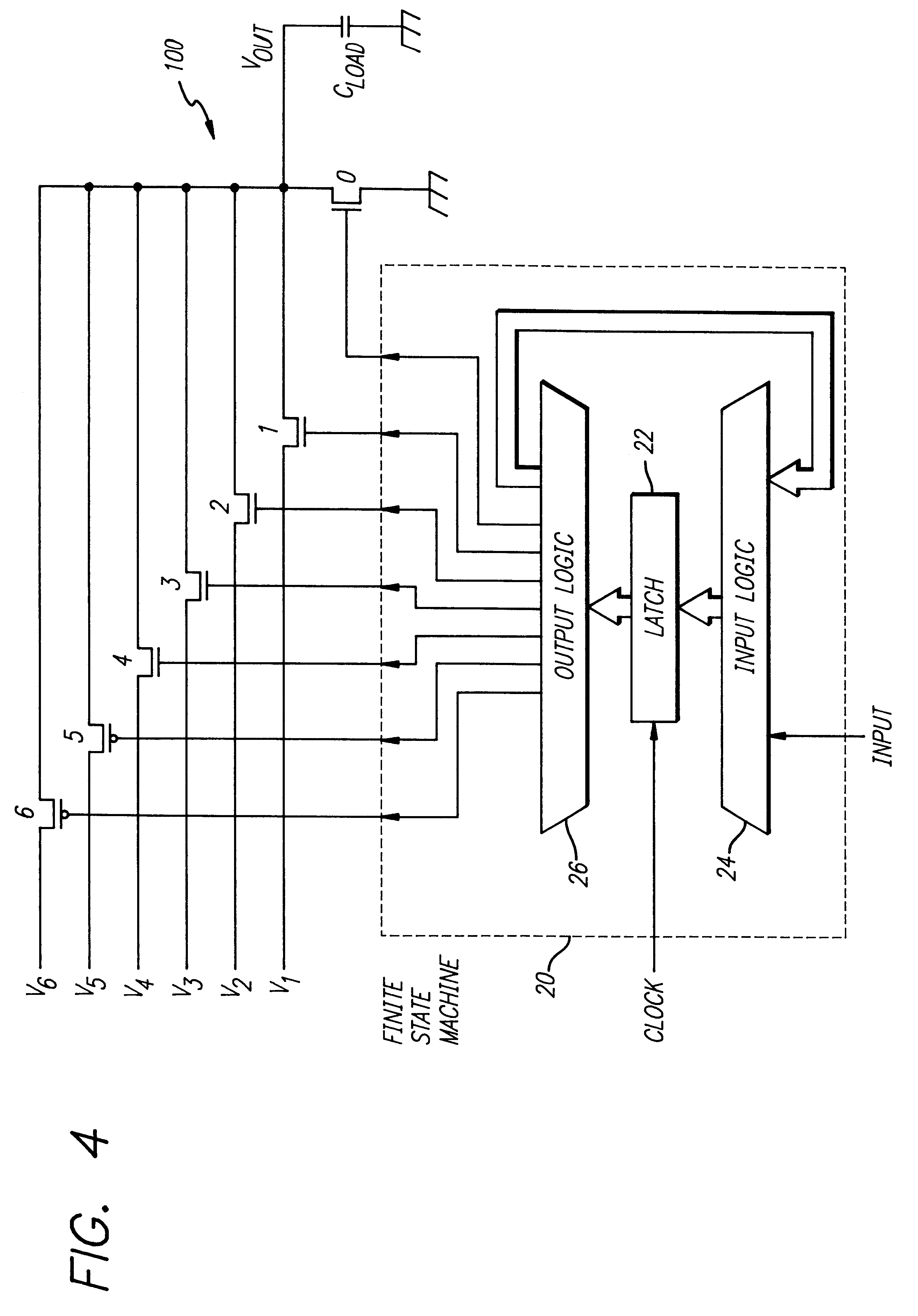
Most of the power dissipation in digital CMOS circuits is due to repeated charging and discharging of capacitive loads including those internal to the circuit and those associated with the output signals.

FIG. 1 is a simplified representation of a conventional driver for a capacitive load. The load C.sub.L represents the capacitance of a load and the interlead capacitance of the lines connecting the driver 10' to the load 12'. The load 12' is cha...


PUM


Abstract

A system and method for efficiently charging and discharging a capacitive load from a single voltage source. The system includes a first switch for selectively connecting the voltage source to the load and a second switch for selectively providing a short across the load as may be common in the art. A particularly novel aspect of the invention resides in the provision of plural capacitive elements and a switching mechanism for selectively connecting each of the capacitive elements to the load whereby the load is gradually charged or discharged. In the illustrative embodiment, the switching mechanism includes a set of switches for selectively connecting each of the capacitive elements to the capacitive load and a switch control mechanism for selectively activating the switches.

Description

BACKGROUND OF THE INVENTION1. Field of the InventionThe present invention relates to electronic circuits and systems. More specifically, the present invention relates to power dissipation in electronic circuits and systems.2. Description of the Related ArtPower dissipation of electronic circuitry is an important design consideration for many applications. Power dissipation provides a measure of the efficiency of the system. The efficiency of the system impacts the design of the power supply for the system. That is, low efficiency leads to higher costs due to the waste of energy and the need for larger power supplies.For battery powered systems, power dissipation limits battery life. This necessitates larger batteries which increases the cost and weight of the system while limiting the applicability thereof. As an example, consider coronary pacemakers where power dissipation is a critical concern due to the difficultly of accessing the battery for replacement and the cost and inconve...

Claims


Application Information

Patent Timeline
Patent Type & Authority Patents(United States)
IPC IPC(8): H02M3/07H02M3/04G05F1/565H02M3/158
CPCG05F1/565H02M3/07H02M3/158
Inventor SVENSSON, LARSATHAS, WILLIAM C.KOLLER, JEFFREY G.
Owner UNIV OF SOUTHERN CALIFORNIA
Why Eureka
Try Eureka