Electric machine

a technology of electric machines and electric motors, applied in the direction of mechanical energy handling, emergency protective arrangements responsive to undesired changes, cooling/ventilation arrangements, etc., can solve the problems of electric machines heating up, cooling systems becoming more sophisticated and complex with increasing size, and many electric appliances used in industry, offices and homes

Inactive Publication Date: 2007-07-10
E ON SVERIGE
View PDF22 Cites 10 Cited by
  • Summary
  • Abstract
  • Description
  • Claims
  • Application Information

AI Technical Summary

Benefits of technology

[0012]A further object of the present invention is to provide an apparatus or a method which allow greater mean annual power output from a rotating synchronous electric machine which is cooled by different coolants without any modifications to the machine.
[0050]According to one embodiment, a generator is controlled with a floating capability chart in dependence on the available cooling capacity. Since a disturbance necessitates increased power output for a short period of time, a dynamic capability chart may be used to control the generator for a short period of time, the dynamic capability chart being dependent on the temperature that the machine is allowed to reach. The allowable temperature may be adjusted, for example, to the actual temperature resistance of the insulation or may be set by the machine operator.

Problems solved by technology

Many electric appliances used in industry, offices and homes also consume reactive power, for example appliances equipped with a motor.
Due to dissipation of energy, electric machines heat up during operation.
The cooling systems become more sophisticated and complex with increasing size.
Thus, during the greater part of the operating time there is surplus capacity in the generator.
However, the document makes no reference to rotating machines and says nothing about how to compensate for temporary disturbances in the power grid, which require increased production of reactive power.

Method used


Image

  • Electric machine
  • Electric machine
  • Electric machine

Examples


Embodiment Construction

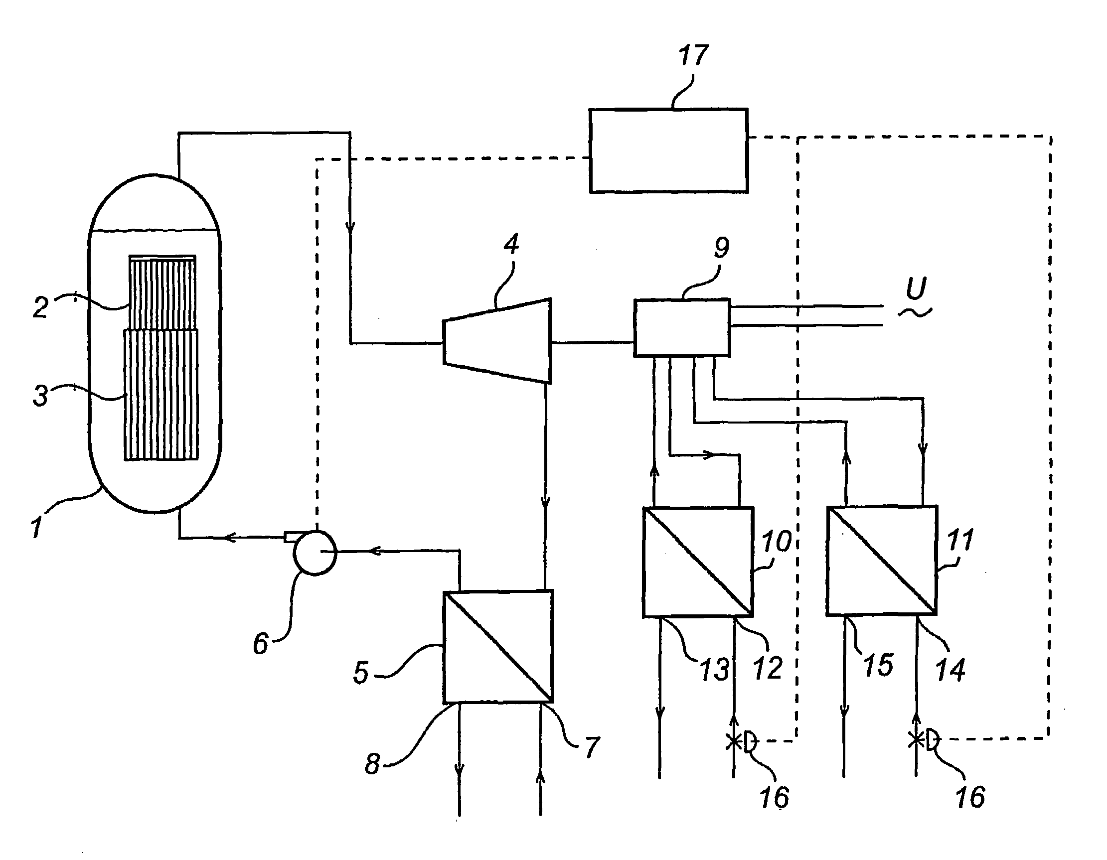
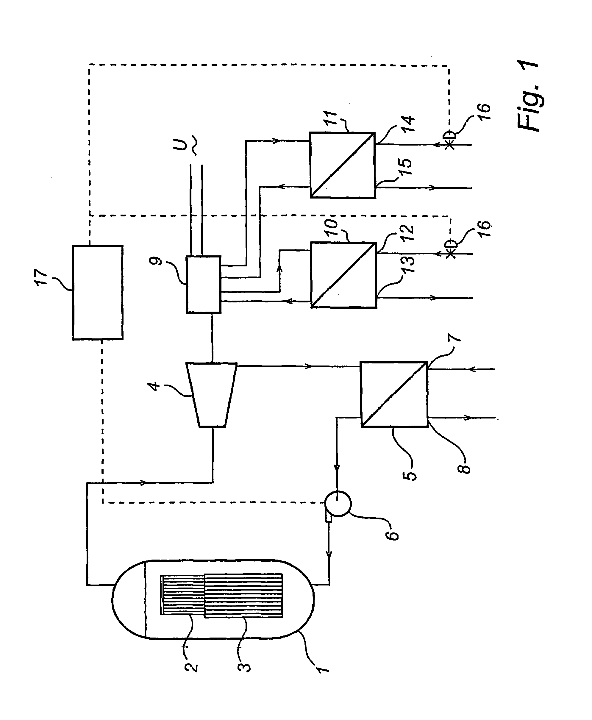
[0071]FIG. 1 is a schematic illustration of a nuclear power plant in which the present invention can be implemented. It should be understood that the nuclear power plant shown in FIG. 1 is highly simplified to clearly illustrate the invention.

[0072]The nuclear power plant comprises a reactor tank 1 with fuel rods 2 and control rods 3. Steam used to operate a turbine 4 is generated in the reactor tank. The steam turbine 4 may contain several turbines, for example one high-pressure turbine and three low-pressure turbines. The turbine 4 in turn operates a generator 9, which produces electric power. The generator is shown in more detail in FIG. 7. After the steam has passed through the turbine 4, it is conveyed to a condenser 5 in which the water vapor is condensed, and then it is recirculated in the form of water to the reactor tank 1 by a pump 6. The condenser 5 is cooled by water from a primary coolant source, the water being supplied to the condenser 5 through a first inlet 7 and di...


PUM


Abstract

A method and an apparatus are described for monitoring a rotating synchronous electric machine (9), which comprises a rotor winding and a stator having a stator winding. The method comprises the steps of determining the stator winding current, determining the stator winding voltage, determining the rotor winding current, and estimating the temperature in at least two positions in the electric machine (9) using a model of the electric machine and the determined current and voltage values. An apparatus according to the invention is provided for carrying out the method.

Description

FIELD OF THE INVENTION[0001]The present invention relates to a rotating synchronous electric machine and a method for such a machine. More specifically, the present invention relates to an apparatus for monitoring and / or controlling and a method of controlling an electric machine of said type and to a plant or an installation comprising such a machine and such an apparatus.BACKGROUND ART[0002]Rotating synchronous electric machines are used in various areas of society. For example, power production generators and motors intended for certain applications are usually of this type.[0003]Electric power intended for distribution is generated by means of generators and transformed with the aid of transformers before being transferred and distributed via power grids at different voltage levels. Transformers and power grids are dependent on reactive power to be able to transform and transport the active power from the generators to the users. The reactive power is also used to control the vo...

Claims


Application Information

Patent Timeline
Patent Type & Authority Patents(United States)
IPC IPC(8): F02D29/06H02P1/00H02H6/00H02H7/06H02P9/10H02P9/14H02P23/14
CPCH02P9/02H02P23/14H02P9/10H02H6/005H02H7/06Y10T24/1471Y10T24/1664Y10T24/186
Inventor SWAHN, HAKANSVENSSON, BERTIL
Owner E ON SVERIGE
Why Eureka
Try Eureka