Position and orientation sensing with a projector

Inactive Publication Date: 2007-07-10
MITSUBISHI ELECTRIC RES LAB INC
View PDF4 Cites 31 Cited by
  • Summary
  • Abstract
  • Description
  • Claims
  • Application Information

AI Technical Summary

Problems solved by technology

Prior art approaches have limitations.
Altering the environment can be difficult when the environment is large or includes hard-to-reach places.
Thus these types of systems tend to be fixed installations with a fixed workspace, and are not easily or quickly deployable in a new setting.
It is problematic to attach multiple markers or emitters to a small object.
It is also problematic if the object is handheld

Method used


Image

  • Position and orientation sensing with a projector
  • Position and orientation sensing with a projector
  • Position and orientation sensing with a projector

Examples


Embodiment Construction

[0015]System Structure

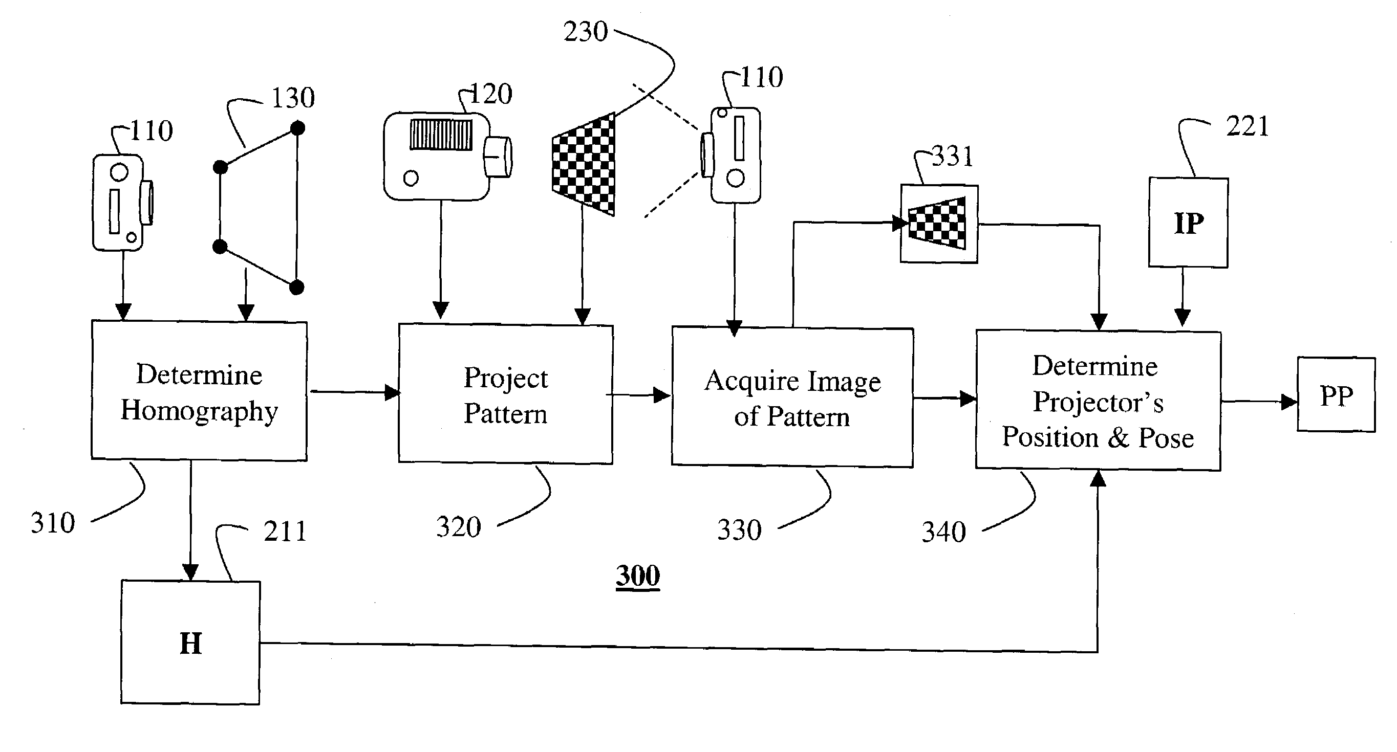
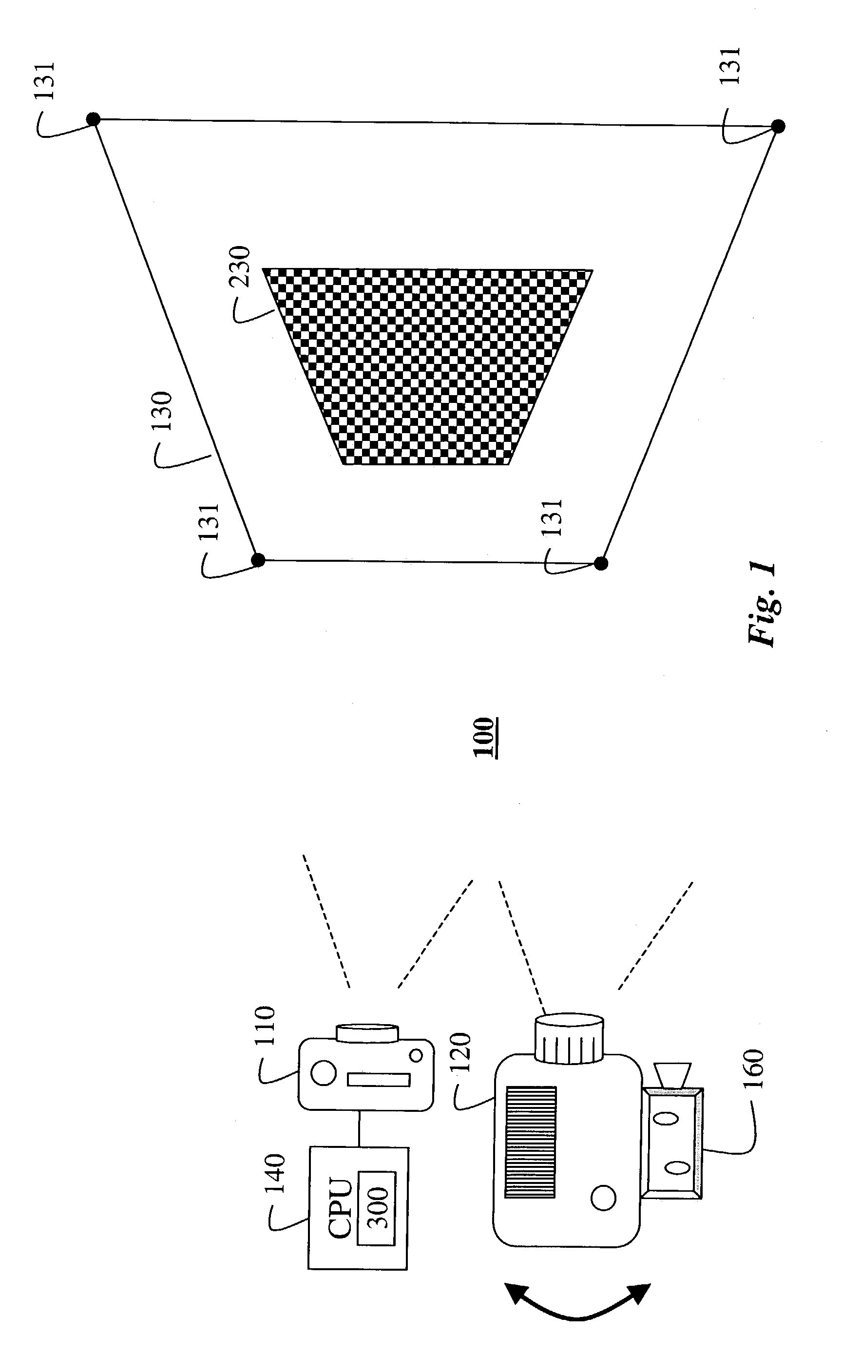
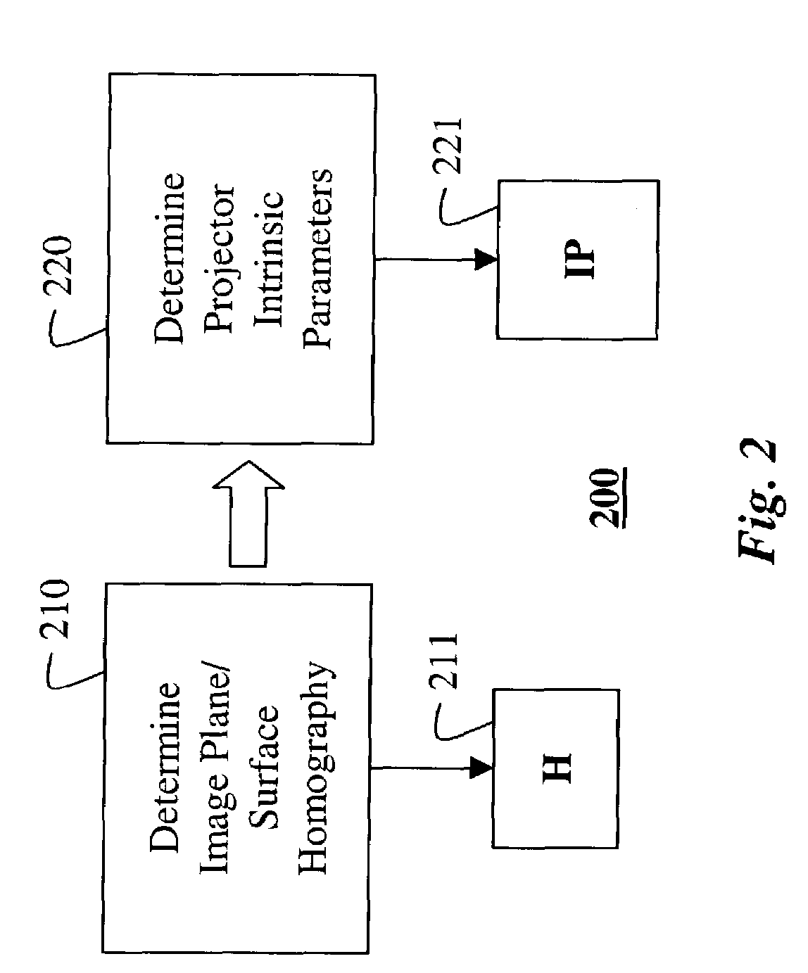
[0016]FIG. 1 shows a position and orientation sensing system 100 according to the invention. The system includes a fixed camera 110 and a movable projector 120. Both the camera 110 and the projector 120 view a fixed, planar (2D) surface 130. The camera and the planar surface have a fixed relative position with respect to each other. The camera and projector can be on the same side of the surface, or alternatively, if the surface is translucent, the camera and the projector can be on opposite sides of the planar surface.

[0017]In a preferred embodiment, the camera 110 and the projector120 are digital devices. Analog devices, with A / D converters, are also possible.

[0018]A processor (CPU) 140 is coupled to the camera 110. The processor 140 is equipped with a memory and I / O ports as are known in the art. The processor 140 is capable of executing a position and orientation sensing method 300 according to the invention, as described below in greater detail.

System Oper...


PUM


Abstract

A position and orientation of a projector are determined from projected images. First, a homography between a camera and a planar surface, where the relationship between the camera and planar surface is fixed, is determined. Next, a known pattern is projected on the planar surface with a projector having known intrinsic parameters and an unknown position and orientation. An image of the known pattern is acquired with the camera, and a position and orientation of the projector is determined from the image using the homography and the intrinsic parameters.

Description

FIELD OF THE INVENTION[0001]The invention relates generally to computer vision, and more particularly to determining the position and orientation of an object using a projected image.BACKGROUND OF THE INVENTION[0002]Position sensors are useful for many applications in which it is necessary to determine the position and orientation of an object. Hereinafter, the term ‘position sensor’ means both position and orientation sensor. The position is the location of the object in a three-dimensional coordinate frame, and the orientation of the object is its rotation relative to that coordinate frame.[0003]In an example application, a position sensor can be attached to a moving camera that is being used for 3D scanning. The position and orientation of the camera are then known, to aid creation of a 3D reconstruction of a scene from the images acquired by the moving camera. Similarly, a position sensor can be attached to a projector to aid correct projection of an image onto a surface or an o...

Claims


Application Information

Patent Timeline
IPC IPC(8): G06K9/36G06T7/00G06V10/145G06V10/147H04N5/74H04N17/00
CPCG06K9/2036G06K9/209G06T7/0042H04N5/74H04N9/3185H04N9/3194G06T7/73G06V10/145G06V10/147
Inventor BEARDSLEY, PAUL A.RASKAR, RAMESHVAISH, VAIBHAV
Owner MITSUBISHI ELECTRIC RES LAB INC
Why Eureka
Try Eureka