Orientation sensing of a rod

a technology of orientation sensing and rods, applied in the field of sensing the orientation of objects, can solve the problems of bulky components and precision machined use of sensors, and achieve the effect of reducing the number of parts and reducing the cost of us

Inactive Publication Date: 2010-04-27
IMMERSION MEDICAL
View PDF7 Cites 23 Cited by
  • Summary
  • Abstract
  • Description
  • Claims
  • Application Information

AI Technical Summary

Problems solved by technology

However, the use of these sensors often requires precision machined and bulky components as part of the implementation.

Method used


Image

  • Orientation sensing of a rod
  • Orientation sensing of a rod
  • Orientation sensing of a rod

Examples


Embodiment Construction

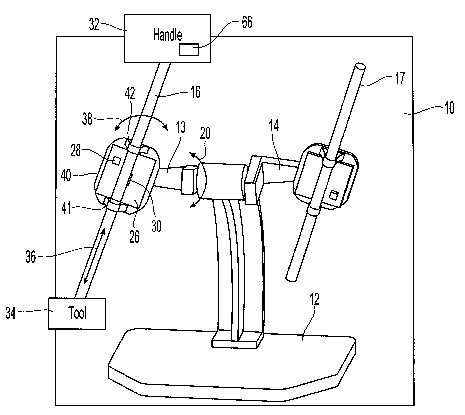
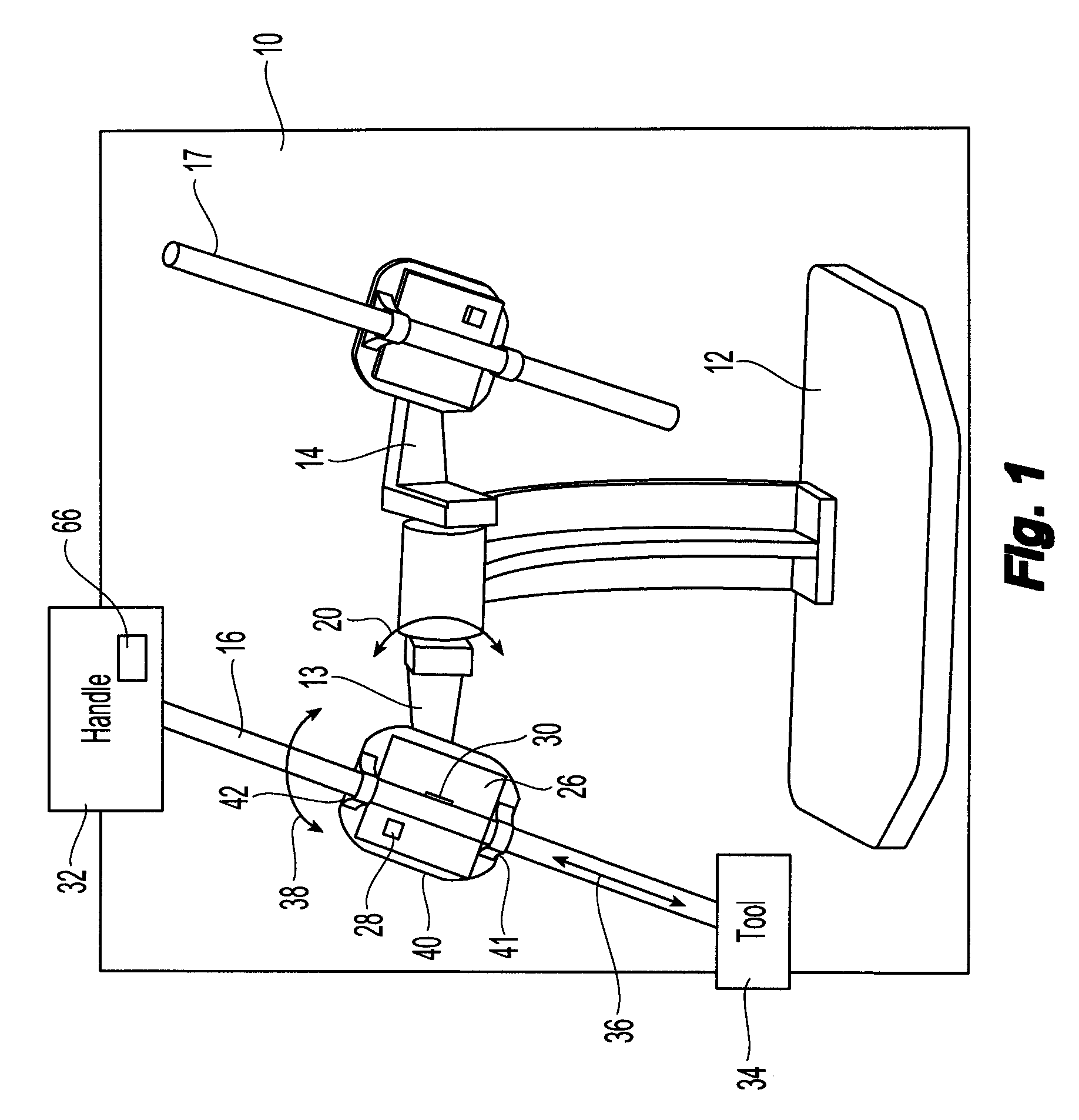
[0012]One embodiment of the present invention is a system for calculating the orientation of a rod through the use of an optical sensor and one or more accelerometers.

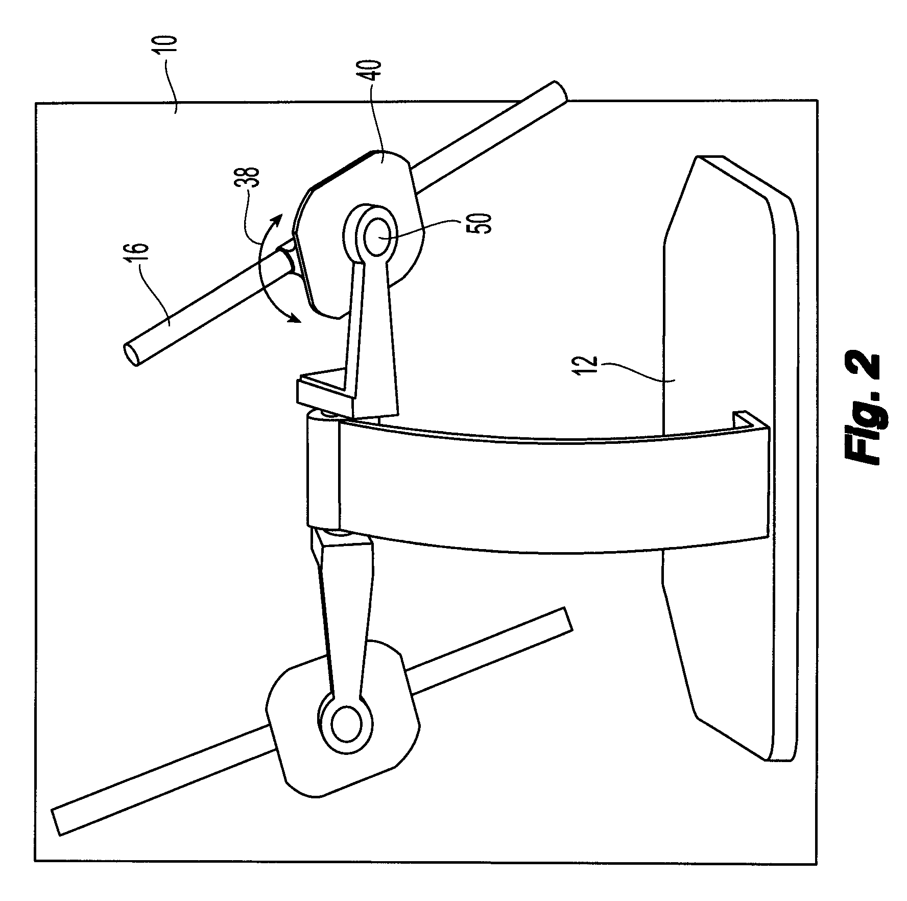
[0013]FIG. 1 is a perspective front view of a two rod laparoscopy simulator 10 in accordance with one embodiment. Simulator 10 includes a base 12 that is fixed to ground. Each rod 16, 17 is coupled to base 12 through an arm 13, 14 that rotates around base 12 via an axis that allows the arms to rotate 360°, as indicated by arrow 20. Rods 16 and 17 and associated components are identical. For rod 16, arm 13 is coupled to a platform 40 through an axis that allows platform 40 to rotate 360°, as indicated by arrow 38. Platform 40 holds rod 16 in place through collars 41, 42. Platform 40 further includes a circuit board 26 that includes an optical sensor 30 and an accelerometer 28. Other simulators may include only one rod, or may have more than two rods or other objects for which the orientation is determined.

[0014]Rod 16 c...


PUM


Abstract

A laparoscopy simulator includes two rods and an orientation sensor that determines the orientation of the rods. An optical sensor is used to determine measurements of each rod based on the rotation of the rod around a central axis of the rod and a sliding of the rod along the central axis. An accelerometer is used to determine additional measurements of each rod based on a rotation of the rod around two additional rotation axes of the simulator. The measurements are used to determine the overall orientation of the rods.

Description

FIELD OF THE INVENTION[0001]One embodiment is directed to sensing the orientation of an object. More particularly, one embodiment is directed to orientation sensing of a rod shaped object.BACKGROUND INFORMATION[0002]The growth of minimally invasive therapies has led to a growing interest in the potential for computer-based simulation for training. Many computer-based medical simulators have been designed to teach these new techniques. Many of these efforts have focused on laparoscopic surgery, in which rigid tools are inserted into the patient's abdomen and visual feedback is provided by an endoscopic camera that produces a high-definition color image. These simulators can be skills trainers or procedure trainers, and emphasize the three-dimensional hand-eye coordination practice that is useful for laparoscopic surgery.[0003]For these simulators, the orientation of the rigid tools, which are typically rods, must be constantly calculated. Various goniometers or goniometry methods hav...

Claims


Application Information

Patent Timeline
Patent Type & Authority Patents(United States)
IPC IPC(8): G01B11/14
CPCG09B23/285G09B23/28
Inventor COHEN, ROBXU, TIANNING
Owner IMMERSION MEDICAL
Why Eureka
Try Eureka