
Electronic Device with a Display Unit Being Movable in Relation to a Base Unit

a technology of electronic devices and base units, applied in the field of electronic devices having display units, can solve the problems of increasing power and complexity of electronic devices, portable electronic devices such as personal digital assistants (pda), laptop computers, in particular, and mobile phone communication devices

Inactive Publication Date: 2010-09-30
SONY ERICSSON MOBILE COMM AB
View PDF15 Cites 22 Cited by
  • Summary
  • Abstract
  • Description
  • Claims
  • Application Information

AI Technical Summary

Benefits of technology

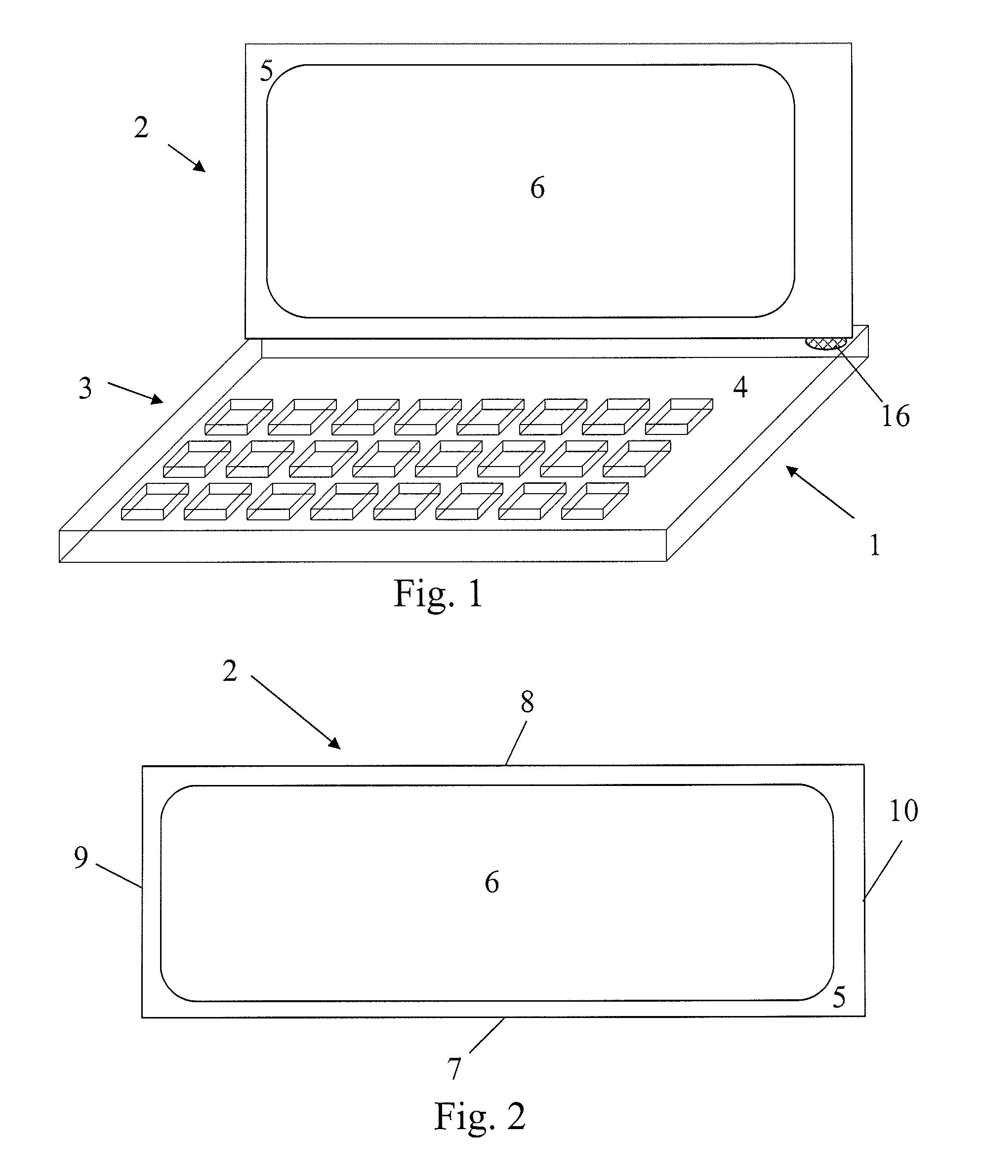
[0006]One object of the present invention is thus directed towards providing an electronic device with increased flexibility in user-device interaction while keeping the device bulkiness at a minimum.
[0042]The present invention has a number of advantages. It controls the use of functionality associated with the electronic device in order to among other things save energy while still allowing a user a great freedom of use of the device. This is furthermore done without the user doing anything else than selecting how to orient the display unit in relation to the base unit. The invention furthermore allows for a compact design of the electronic device without sacrificing usability.

Problems solved by technology

Electronic devices, in general, and portable electronic devices such as personal digital assistants (PDA), laptop computers, in particular, as well as portable communication devices such as mobile phones, are becoming increasingly powerful and complex.
For portable electronic devices one challenge is to increase the display area without increasing the bulkiness of the portable electronic device and at the same time keeping energy consumption at a minimum.

Method used


Image

  • Electronic Device with a Display Unit Being Movable in Relation to a Base Unit
  • Electronic Device with a Display Unit Being Movable in Relation to a Base Unit
  • Electronic Device with a Display Unit Being Movable in Relation to a Base Unit

Examples


first embodiment

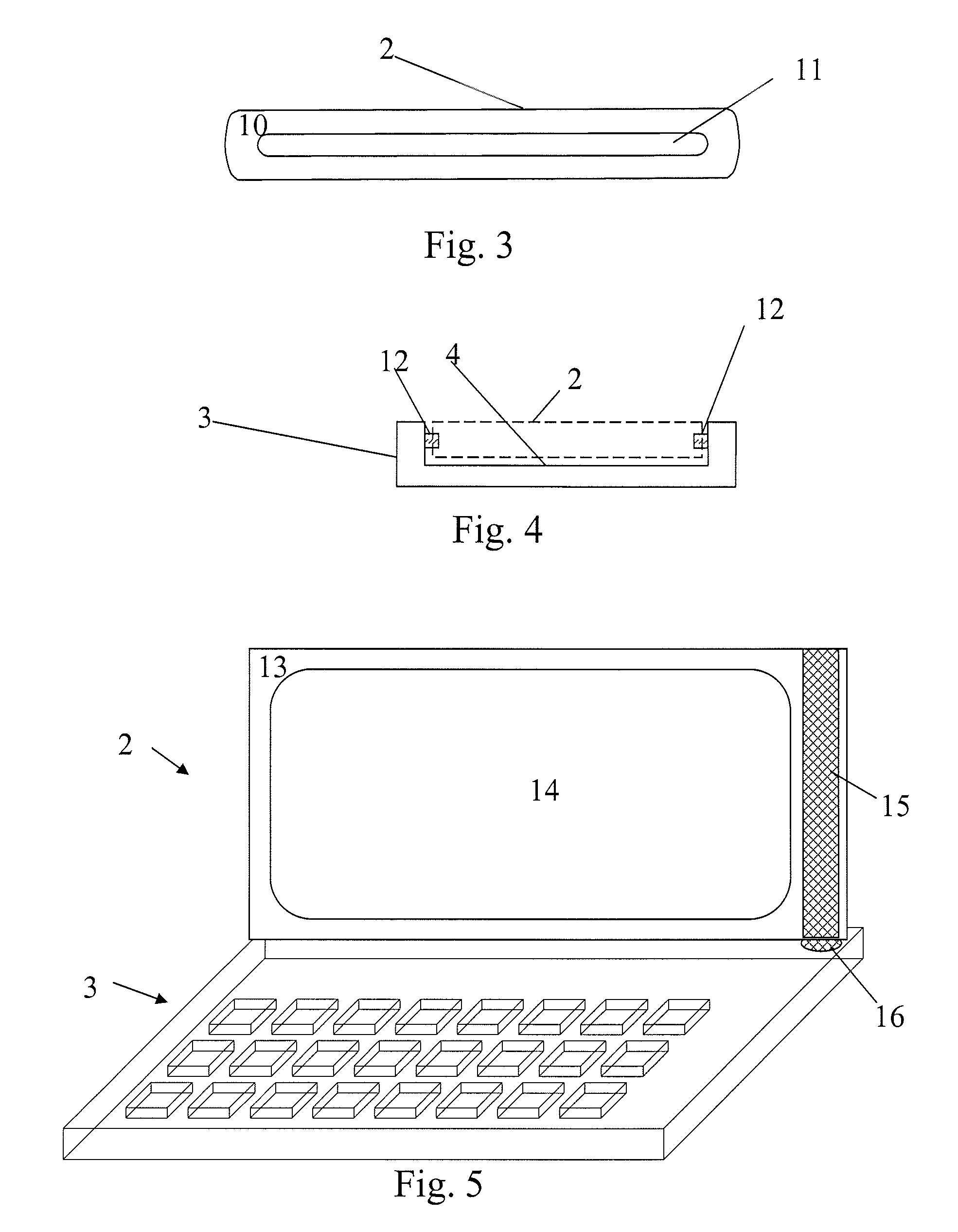
[0062]According to the present invention the first elongated line sensor 15 stretches beyond the second surface area 5 and up onto the first bounding side. This will be shown in more detail later.

[0063]The displays described above preferably, have opposite projection directions. The displays accommodated on the first surface area and second surface area were above shown as having the same sizes. However, it should be realized that they can differ in size and also differ in the display technologies used.

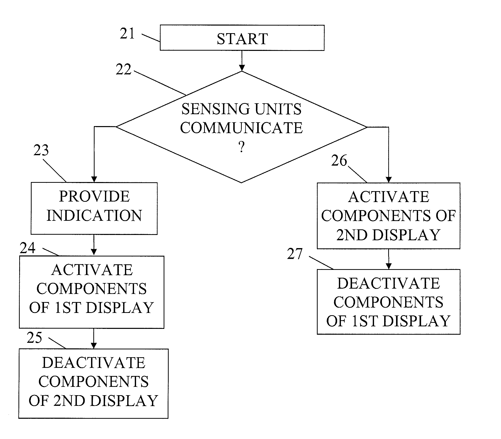
[0064]FIG. 6 shows a block schematic of a number of elements provided in the electronic device of the present invention. The orientation sensing arrangement 17, which thus includes the two sensing units 15 and 16, is connected to an orientation determining unit 18. The orientation determining unit 18 is connected to components associated with the first display and here driving circuits 19 for the first display 6 as well as to components associated with the second display and here driv...

third embodiment

[0077]According to the present invention that is shown in FIG. 10, the first sensing unit 15″ is again an elongated line sensor, while the second sensing unit 16 is a spot sensor. However in this embodiment the first sensing unit 15″ is a sensor array, with a number of small independent sensors. In this way it is possible to detect which of these small sensors is in contact with the spot sensor 16. In this way it is furthermore possible to get an indication of the position of the display unit 2 in relation to the base unit in the direction of elongation in order to make a finer determination of what functionality that is to be activated and deactivated.

[0078]There are a number of variations that are possible to make of the present invention apart from those already discussed above. The invention has for instance been described in relation to a portable electronic device in the form of a lap top computer. However, the present invention can be applied also on other portable electronic...

second embodiment

[0079]The first sensing unit was above described as stretching out onto the first bounding side. In alternatives of the present invention it may not do so, but only be provided on the second surface area. As yet an alternative it may, in addition to stretching out onto the first bounding side also stretch out onto the second bounding side. In the case of the second embodiment, there may in this case be two sensing units provided on the display unit.

[0080]The components controlled need furthermore not be limited to components associated with the displays. Other components could include illuminations means providing such functionality as highlighting keypad features or keypad buttons. For an electronic device as shown in FIG. 1 the buttons in the keypad could change assigned values depending on the relative position of the display unit. Similarly functionality such as software applications or operating systems could be activated or deactivated automatically depending on the relative p...


PUM


Abstract

The invention relates to an electronic device and a method for controlling functionality of such an electronic device in relation to a display unit. The electronic device includes a base unit (3); a display unit (2), an orientation sensing arrangement and an orientation determining unit. The display unit (2) has a first surface area and a second surface area (13) joined to each other by a first and second opposite bounding side and is fastened to and movable in relation to the base unit (3). The orientation sensing arrangement comprises a first sensing unit (15) on the display unit (2) and a second sensing unit (16) on the base unit (3), which arrangement detects that the sensing units are able to communicate with each other and indicates this communication. The orientation determining unit then activates selected functionality of the electronic device based on the indication from the orientation sensing arrangement.

Description

FIELD OF THE INVENTION[0001]The invention relates to electronic devices having display units that are moveable in relation to base units. The present invention is more particularly related to an electronic device and a method for controlling functionality of an electronic device in relation to a display unit.BACKGROUND OF THE INVENTION[0002]Electronic devices, in general, and portable electronic devices such as personal digital assistants (PDA), laptop computers, in particular, as well as portable communication devices such as mobile phones, are becoming increasingly powerful and complex. More functionality is incorporated into the devices and this requires them to be more flexible in terms of user interaction, both in displaying information and also in receiving data. This becomes especially apparent in portable electronic devices, which are normally smaller than other consumer electronics products. More refined keyboards, user interaction means and connections are added to portabl...

Claims


Application Information

Patent Timeline
IPC IPC(8): G09G5/00
CPCH04M1/021H04M1/0214H04M2250/16H04M1/0241H04M2250/12H04M1/0235
Inventor HERINGSLACK, HENRIKLARSSON, MATSSORENSSON, STEFAN
Owner SONY ERICSSON MOBILE COMM AB
Learn More