Image-forming device and process cartridge

a technology of image-forming device and process cartridge, which is applied in the direction of electrographic process apparatus, instruments, optics, etc., can solve the problems of increasing manufacturing costs, running the risk of causing damage or significant wear to the rotary drive member,

Active Publication Date: 2007-07-10
BROTHER KOGYO KK
View PDF24 Cites 75 Cited by
  • Summary
  • Abstract
  • Description
  • Claims
  • Application Information

AI Technical Summary

Benefits of technology

[0007]However, with the construction of the image-forming device disclosed in Japanese unexamined patent application publication No. 2002-149037, if the cover is opened during a printing operation, the rotary drive member is disengaged from the rotating member of the process cartridge while both members are rotating, running the risk of causing damage to or significant wear on the rotary drive member. Moreover, forming the rotary drive member with a high-strength material to prevent such damage to and wear on the rotary drive member will inevitably increase manufacturing costs.
[0008]In view of the foregoing, it is an object of the present invention to provide an image-forming device and a process cartridge, which are capable of interrupting the transfer of a drive force to the process cartridge when the process cartridge is being removed from the image-forming device and which are capable of preventing transfer of the drive force to the process cartridge from being interrupted while the process cartridge is operating in the image-forming device.

Problems solved by technology

However, with the construction of the image-forming device disclosed in Japanese unexamined patent application publication No. 2002-149037, if the cover is opened during a printing operation, the rotary drive member is disengaged from the rotating member of the process cartridge while both members are rotating, running the risk of causing damage to or significant wear on the rotary drive member.
Moreover, forming the rotary drive member with a high-strength material to prevent such damage to and wear on the rotary drive member will inevitably increase manufacturing costs.

Method used


Image

  • Image-forming device and process cartridge
  • Image-forming device and process cartridge
  • Image-forming device and process cartridge

Examples


Embodiment Construction

[0022]An image-forming device and a process cartridge according to a preferred embodiment of the present invention will be described while referring to the accompanying drawings wherein like parts and components are designated by the same reference numerals to avoid duplicating description.

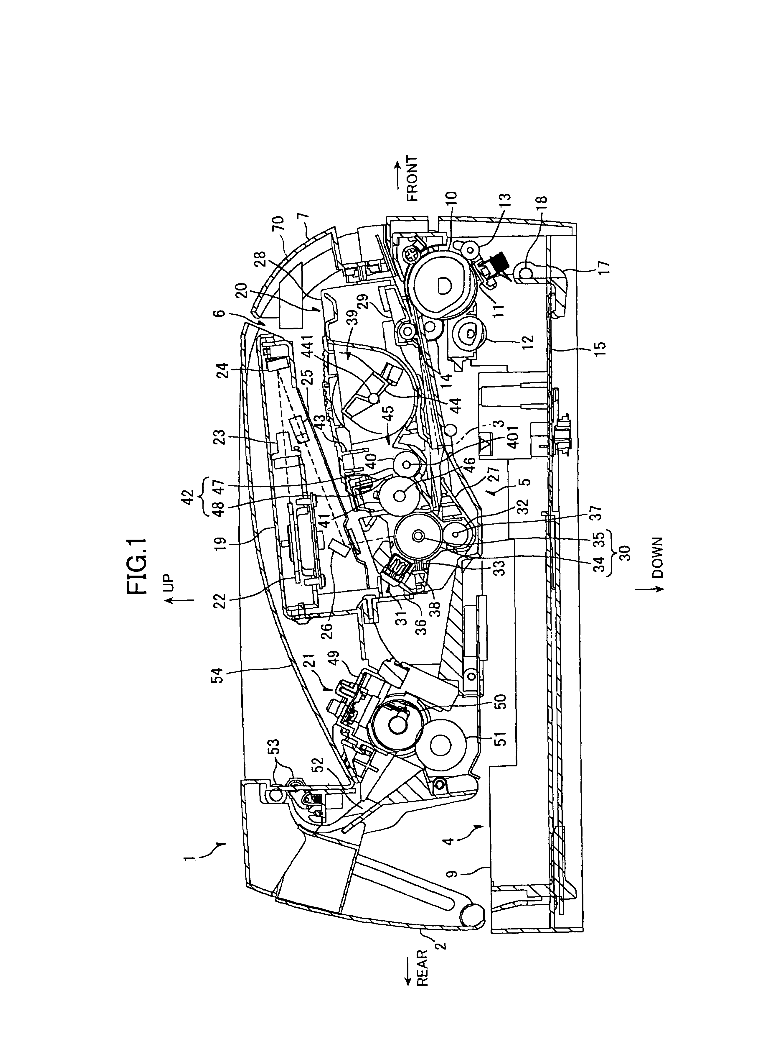
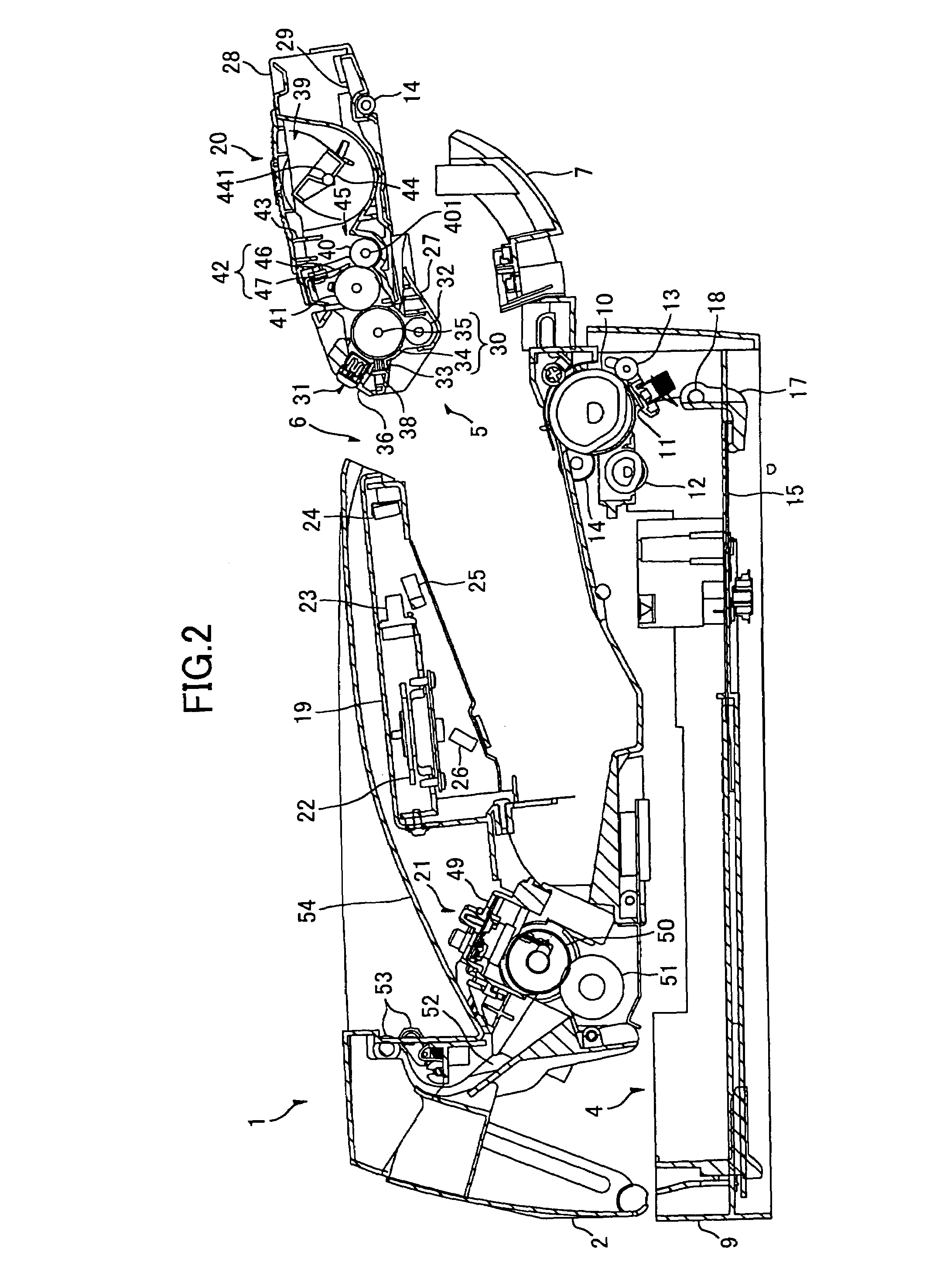
[0023]FIGS. 1 and 2 are side cross-sectional views showing the relevant construction of a laser printer 1 according to the preferred embodiment.

[0024]As shown in the drawings, the laser printer 1 includes a main casing 2. Within the main casing 2, the laser printer 1 includes: a feeder unit 4 for feeding a paper 3; and an image-forming unit 5 for forming images on the paper 3 supplied from the feeder unit 4.

[0025]The laser printer 1 also includes an access opening 6 formed in one side wall of the main casing 2 for inserting and removing a process cartridge 20 described later, and a front cover 7 capable of opening and closing over the access opening 6. The front cover 7 is rotatably supported by a...


PUM


Abstract

An image-forming device includes: a cartridge receiving portion; a drive engaging unit; and a coupling member. The cartridge receiving portion receives a process cartridge detachably mounted therein. The drive engaging unit can move between an engaged position, in which the drive engaging unit transfers a driving force to the process cartridge, and a disengaged position, in which the drive engaging unit fails to transfer a driving force to the process cartridge. The coupling member moves the drive engaging unit between the engaged position and the disengaged position in association with mounting and detaching of the process cartridge in the cartridge receiving portion.

Description

BACKGROUND OF THE INVENTION[0001]1. Field of the Invention[0002]The present invention relates to an image-forming device such as a laser printer, and a process cartridge detachably mountable in the image-forming device.[0003]2. Description of Related Art[0004]A process cartridge can be detachably mounted in an image-forming device such as a laser printer. The process cartridge is provided with: a photosensitive drum on which electrostatic latent images are formed based on image data; and a developing roller for developing the electrostatic latent images into toner images. When the process cartridge is mounted in this image-forming device, the photosensitive drum and developing roller are arranged in opposition to each other and are driven to rotate in prescribed directions. While the photosensitive drum rotates one revolution, an electrostatic latent image is formed on the surface of the drum. When the latent image comes into contact with the developing roller, toner is supplied fro...

Claims


Application Information

Patent Timeline
Patent Type & Authority Patents(United States)
IPC IPC(8): G03G15/00G03G21/18G03G15/08
CPCG03G21/186G03G2221/1657G03G2221/1884
Inventor YOKOTA, EIJI
Owner BROTHER KOGYO KK
Why Eureka
Try Eureka