Modular electronics enclosure

a module and enclosure technology, applied in the direction of side-by-side/stacked arrangements, electrical apparatus construction details, cabinet/cabinet/drawer, etc., can solve the problems of reducing the packing efficiency of the enclosure, and affecting the use of the enclosure. , to achieve the effect of convenient use and assembly, and cost saving

Inactive Publication Date: 2007-07-17
EXCELIS INC
View PDF31 Cites 42 Cited by
  • Summary
  • Abstract
  • Description
  • Claims
  • Application Information

AI Technical Summary

Problems solved by technology

Threaded fasteners have several disadvantages when assembling modules for housing circuit card assemblies.
When an enclosure contains fewer circuit card assemblies than it is designed to hold, a portion of the enclosure is wasted, and therefore decreases the packing efficiency of the enclosure.
One shortfall is that space must be reserved to accommodate fasteners, (e.g., screw heads, washers) on both the upper and lower surfaces of the circuit card assemblies.
Should a circuit card assembly be re-laid (i.e., turned), the pre-existing mounting boss locations may become an impediment to circuit routing and component placement.
This design requirement is a significant limitation of the existing enclosure designs.
Yet another drawback of the prior art enclosures is the inability to provide adequate electromagnetic interference (EMI) shielding.
This configuration restricts the flexibility of the enclosure to accommodate a varying number of circuit card assemblies.

Method used


Image

  • Modular electronics enclosure
  • Modular electronics enclosure
  • Modular electronics enclosure

Examples


Embodiment Construction

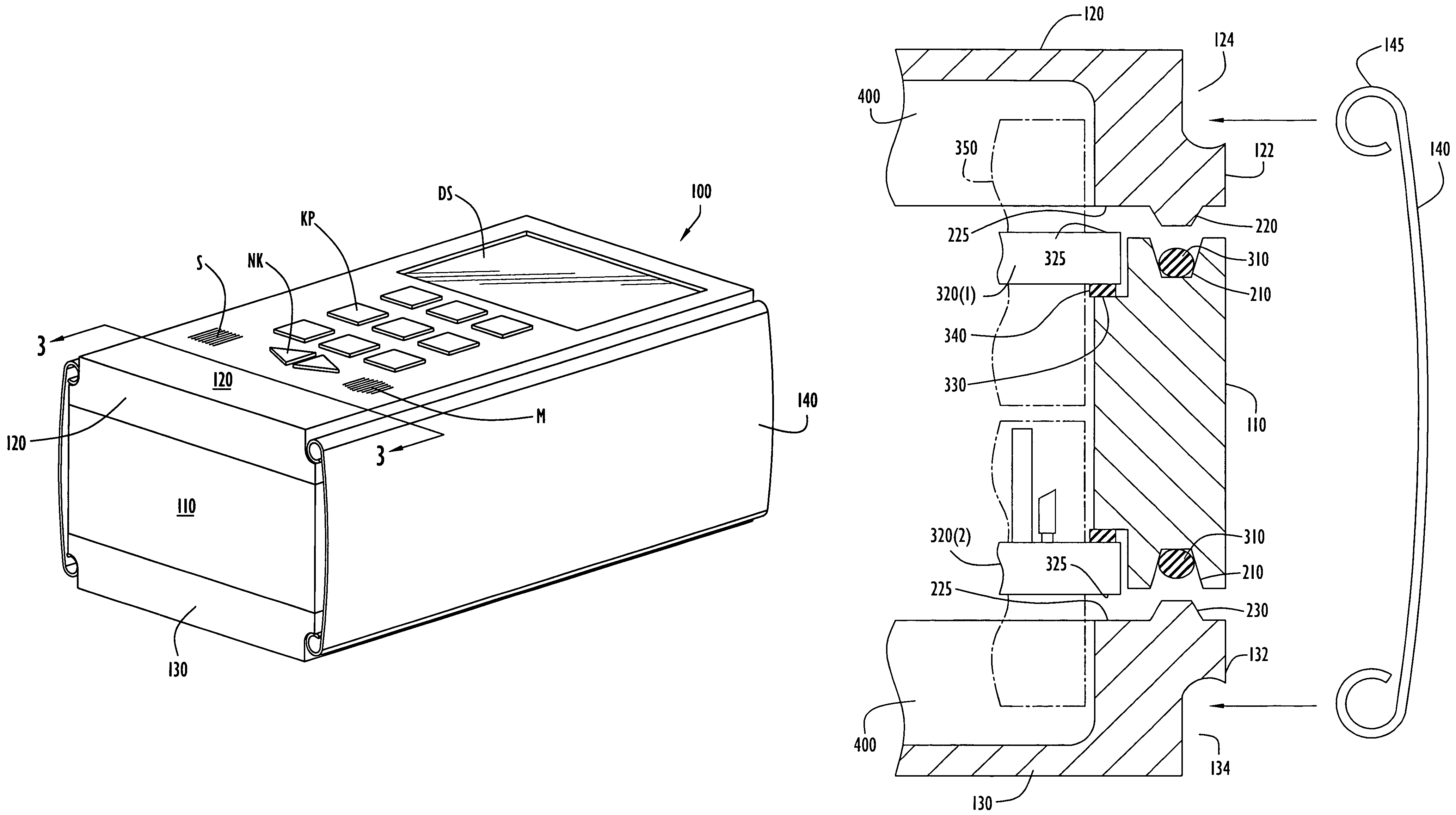
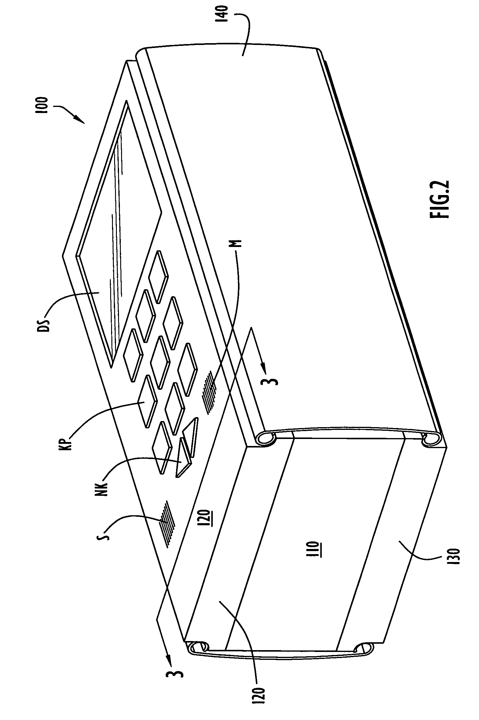
[0025]A modular electronics enclosure is provided having at least one intermediate section that engages substantially similar top and bottom lid members via complementary structures, such as tongue and groove structures. A spring biased clip clamps the top and bottom lid members to hold the entire enclosure together. The one or more intermediate sections are constructed to be interchangeable to increase or decrease the capacity of the modular enclosure, as well as allowing for profile specific designs.

[0026]FIG. 2 is a perspective view of an embodiment of modular enclosure 100. Modular enclosure 100 comprises an intermediate support section or member 110 that supports at least one circuit card assembly (CCA), a top lid member 120 and bottom lid member 130. A clip 140 engages the top 120 and bottom 130 to secure the intermediate section 110 in a sandwich arrangement. Two clips 140 are shown that engage opposite sides of the top lid 120 and bottom lid 130. The clips 140 are an example...


PUM


Abstract

A modular electronics enclosure for one or more circuit card assembly includes top and bottom lids formed substantially the same with at least one intermediate circuit card support member disposed therebetween. At least one spring clip clamps the top and bottom lids together around the intermediate support member.

Description

BACKGROUND OF THE INVENTION[0001]1. Field of the Invention[0002]The present invention pertains to an enclosure for electronics. In particular, the present invention pertains to a modular enclosure for housing electronic components. The modular container comprises interchangeable elements to expand or reduce the interior volume of the container.[0003]2. Description of the Related Art[0004]As seen in FIG. 1, conventional electronics enclosures 10 are typically constructed to include four sides 12, a top 14 and a bottom 16. In some instances, the bottom 16 is formed integrally with the sides 12. The top 14 and bottom 16, or top 14 only in the case of the latter, are then secured to the sides 12 in order to seal the enclosure and any circuit card assemblies therein.[0005]Typical enclosures are sealed through a variety of methods. In one version, the top and bottom 12 and 14 are held in place around an intermediate section that forms or is integral with the sides 12 via a nut 20 and bolt...

Claims


Application Information

Patent Timeline
Patent Type & Authority Patents(United States)
IPC IPC(8): H05K5/00
CPCH05K5/0021H05K7/142H05K5/0004H05K5/0008H05K5/0013
Inventor KLEIN, ROBERT D.KARTMAN, ROBERT E.GESWEIN, CHARLES A.
Owner EXCELIS INC
Why Eureka
Try Eureka