Shoe lace

a technology of shoe lace and lace, which is applied in the field of shoe lace, can solve the problems of user inconvenience and decrease the lifetime of shoe la

Inactive Publication Date: 2007-07-24
KAE SHENG WEBBING
View PDF6 Cites 26 Cited by
  • Summary
  • Abstract
  • Description
  • Claims
  • Application Information

AI Technical Summary

Benefits of technology

[0005]The primary objective of the present invention is to provide a shoe lace, wherein the two ends of the shoe lace can be combined with each other, so that a user needs not to bind the shoe lace, thereby facilitating the user wearing the shoes by the shoe lace.
[0006]Another objective of the present invention is to provide a shoe lace, wherein the two ends of the shoe lace can be detached from each other easily and rapidly, thereby facilitating the user releasing the shoe lace.
[0007]A further objective of the present invention is to provide a shoe lace, wherein the two ends of the shoe lace can be combined with each other, thereby preventing the shoe lace from being becoming loosened.
[0008]A further objective of the present invention is to provide a shoe lace, wherein the second connecting member has a pattern formed thereon, so that the aglet of the shoe lace has an outstanding outer appearance, thereby enhancing the aesthetic quality of the shoe lace.
[0009]A further objective of the present invention is to provide a shoe lace, wherein the shoe lace has a detachable aglet that can be replaced when being worn out, thereby enhancing the lifetime of the shoe lace.

Problems solved by technology

However, the aglet is fixed on the shoe lace, so that it is necessary to dispose the whole shoe lace when the aglet is worn out, thereby decreasing the lifetime of the shoe lace.
In addition, when the shoe lace is bound on a shoe, the shoe lace easily becomes loosened during a period of time so that the user has to bind the shoe lace again, thereby causing inconvenience to the user.

Method used


Image

  • Shoe lace
  • Shoe lace
  • Shoe lace

Examples


Embodiment Construction

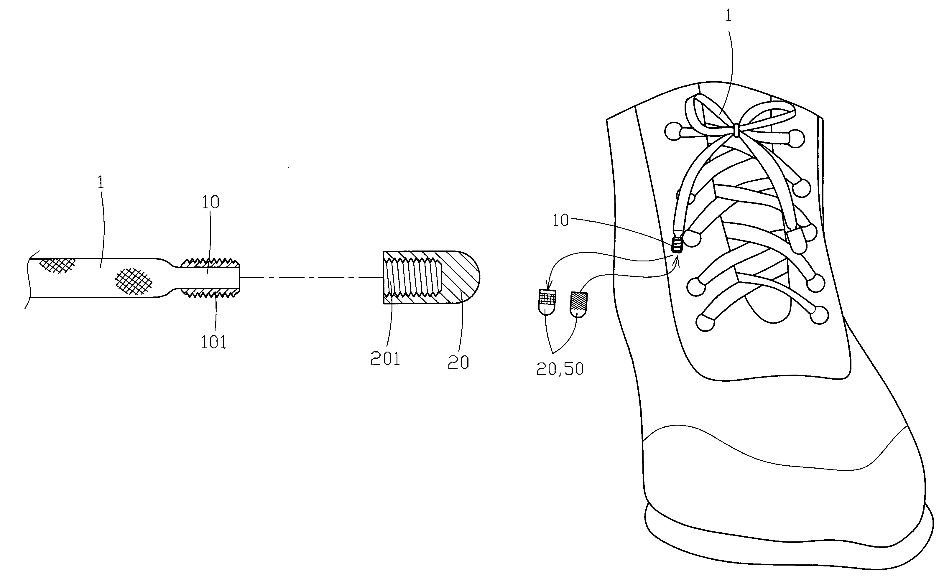
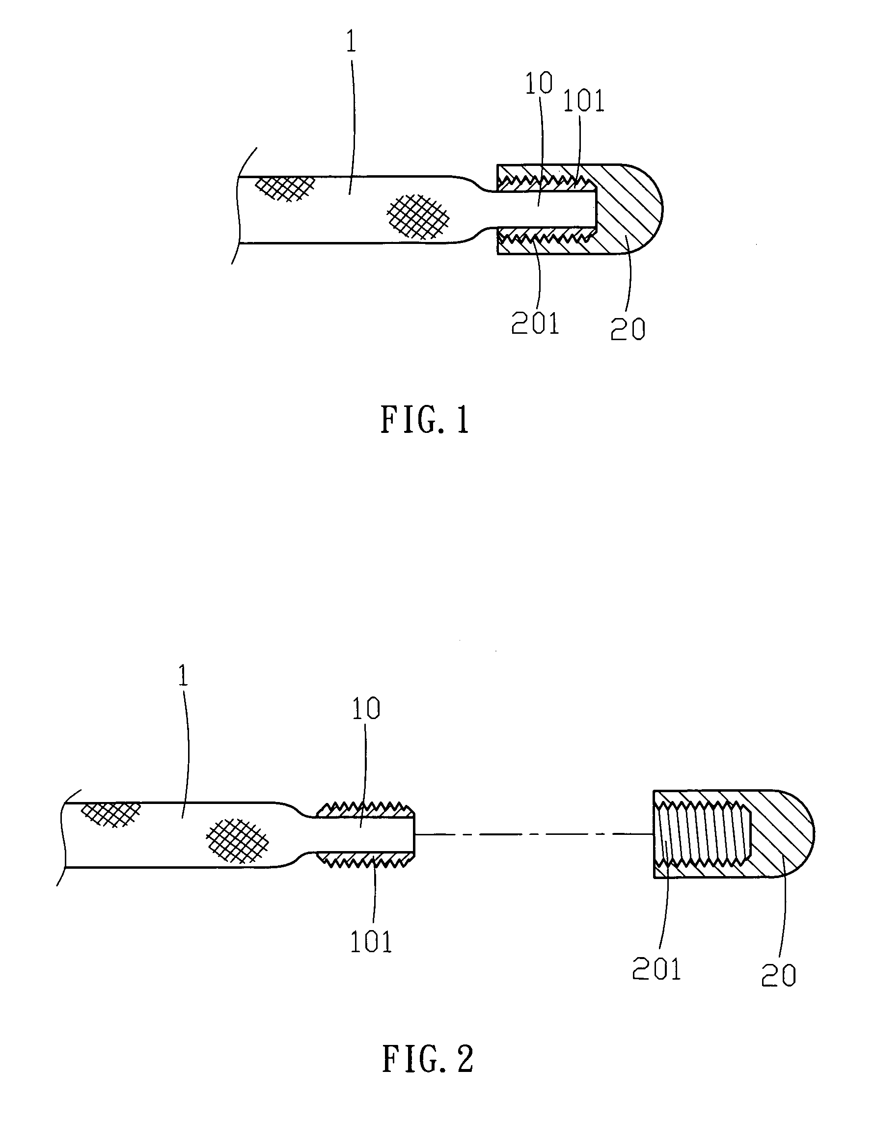
[0025]Referring to the drawings and initially to FIGS. 1 and 2, a shoe lace in accordance with the preferred embodiment of the present invention comprises a lace body 1 having two ends each provided with a first connecting member 10, and a second connecting member 20 detachably mounted on the first connecting member 10. The first connecting member 10 has an outer wall provided with a first fastener 101, and the second connecting member 20 has an inner wall provided with a second fastener 201 detachably secured on the first fastener 101. The second connecting member 20 has a pattern formed thereon. Preferably, the first fastener 101 is an outer thread, and the second fastener 201 is an inner thread screwed onto the first fastener 101.

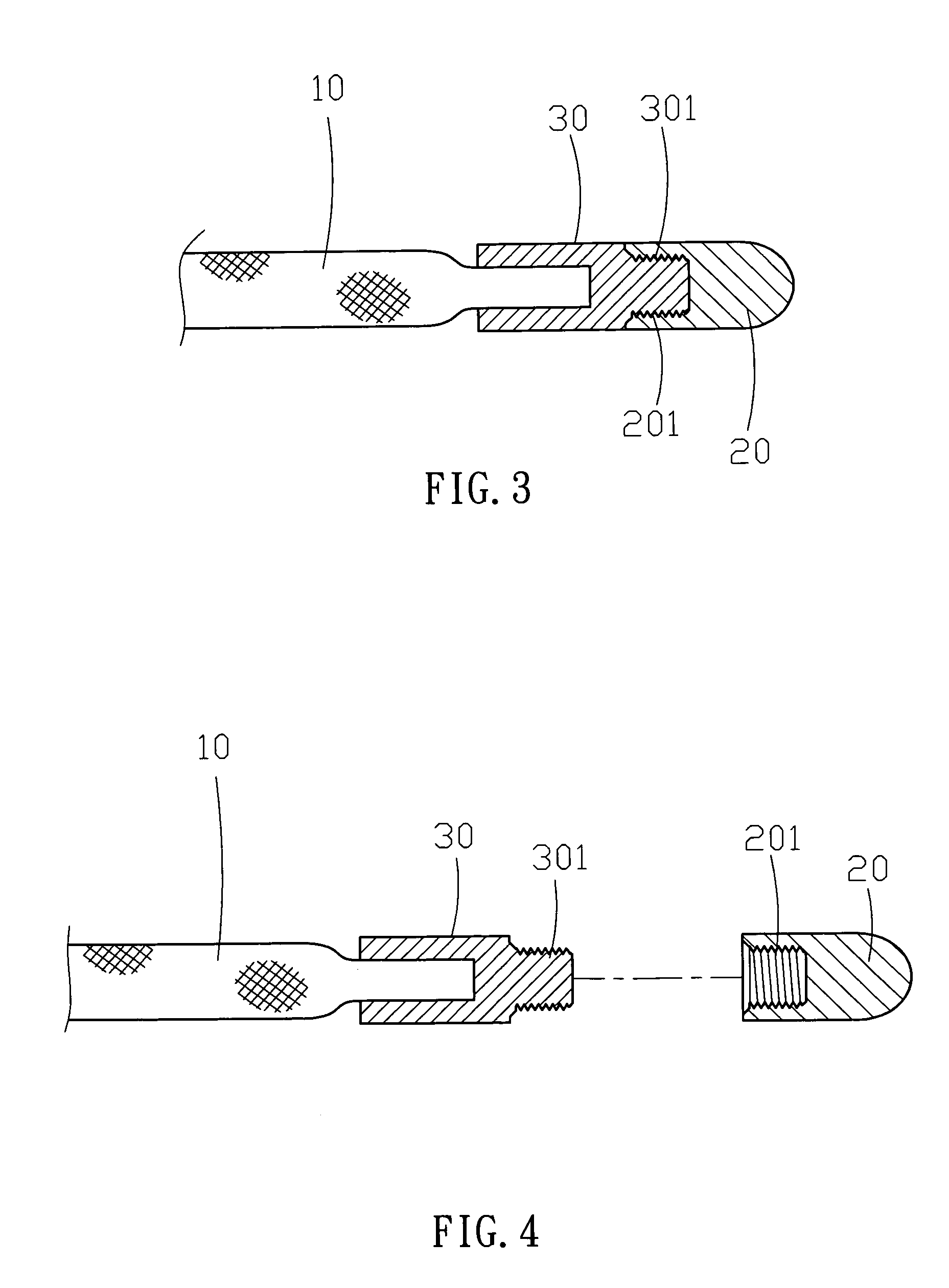
[0026]Referring to FIGS. 3 and 4, the first fastener 30 has a first end mounted on the first connecting member 10 and a second end formed with an outer thread 301 screwed into the second fastener 201.

[0027]Referring to FIGS. 5 and 6, the first fastener 4...


PUM


Abstract

A shoe lace includes a lace body having a first end provided with a first connecting member and a second end provided with a second connecting member, and a third connecting member mounted on the second connecting member and detachably combined with the first connecting member. Thus, the two ends of the shoe lace can be combined with each other, so that a user needs not to bind the shoe lace, thereby facilitating the user wearing the shoes by the shoe lace. In addition, the two ends of the shoe lace can be detached from each other easily and rapidly, thereby facilitating the user releasing the shoe lace.

Description

BACKGROUND OF THE INVENTION[0001]1. Field of the Invention[0002]The present invention relates to a shoe lace, and more particularly to a shoe lace having a detachable aglet.[0003]2. Description of the Related Art[0004]A conventional shoe lace has two ends each provided with an aglet. However, the aglet is fixed on the shoe lace, so that it is necessary to dispose the whole shoe lace when the aglet is worn out, thereby decreasing the lifetime of the shoe lace. In addition, when the shoe lace is bound on a shoe, the shoe lace easily becomes loosened during a period of time so that the user has to bind the shoe lace again, thereby causing inconvenience to the user.SUMMARY OF THE INVENTION[0005]The primary objective of the present invention is to provide a shoe lace, wherein the two ends of the shoe lace can be combined with each other, so that a user needs not to bind the shoe lace, thereby facilitating the user wearing the shoes by the shoe lace.[0006]Another objective of the present ...

Claims


Application Information

Patent Timeline
Patent Type & Authority Patents(United States)
IPC IPC(8): A43C9/00A43C9/04A43C9/06A43B5/00
CPCA43C1/00A43C7/00A43C9/06Y10T24/3795Y10T24/3797
Inventor HUANG, KE-CHIEH
Owner KAE SHENG WEBBING
Why Eureka
Try Eureka