Gas lift plunger assembly arrangement

a technology of assembly arrangement and plunger, which is applied in the direction of sealing/packing, positive displacement liquid engine, borehole/well accessories, etc., can solve the problems of wear of the plunger, time-consuming process of re-building or re-conditioning typical worn prior art plungers, and high equipment costs, so as to promote “even” wear.

Active Publication Date: 2012-04-24
WELL MASTER CORP
View PDF3 Cites 4 Cited by
  • Summary
  • Abstract
  • Description
  • Claims
  • Application Information

AI Technical Summary

Benefits of technology

[0007]It is a further object of the present invention, to provide a plunger assembly which may be repaired easily in the field, with minimal tools and equipment, and without wasting time or device components.
[0008]It is a further object of the present invention to permit the simple repair and / or replacement of one or more of “wear pads” on a “tubing-worn” plunger in the field, as one or more replacement pads may be needed, without having to dis-assemble and re-assemble the entire plunger to do the job.BRIEF SUMMARY OF THE INVENTION
[0011]An arrangement of curved sealing-surface pads are arranged to be supported on the radially outer end of the radially directed standoffs. The curved sealing-surface pads each have a cutout arranged on its longitudinally directed edges. Each cutout slidingly mates with the radially directed standoffs. A radial bias spring is arranged between the central spine or mandrel adjacent each radially directed standoff. The radial bias springs act to radially outwardly bias the curved sealing surface pads against the inner side of the conduit in which the split-pad plunger travels. The outward radial bias of the sealing-surface pads acts to minimize loss of pressure from the lower side of that conduit during its movement therein. The half retrieval-neck has an annular ring on its inner open end, which ring engages a lip on the distal side of the curved sealing-surface pads, and keeps them secured to the central spine or mandrel at each (outer or respective distal) end of that split-pad plunger arrangement.
[0013]That arcuately segmented split retainer ring thus permits easy assembly and disassembly of the respective curved sealing-surface pads from their respective half portions of the central spine or mandrel, as those curved sealing-surface pads have been worn down by frictional engagement with the inside wall of the tubing or conduit in which the plunger travels. Removal of the bolt and lock washer from the arcuately segmented split retainer ring facilitates the simple removal of the retrieval neck from the distal end of each respective curved surface pad. This thus permits the curved surface pads to be removed from their engagement with the radial bias springs, and replaced by new pads right at the “field” site.
[0017]The elongated plunger assembly may have a releasable lock washer as a visable “spring-capacity” indicator notch thereon to indicator to field repair personnel what capacity springs are being utilized to bias each wear pad outwardly. The wear pad in one preferred embodiment, may have a spiral array of grooves thereon to indicate levels of wear thereon, acting as a “wear indicator” on the pad. Signal generated sensors, such as “circuit-completion” contacts or rf signal generators through a proper buried circuit, or conspicuous visual indicators may also be embedded within the pads or grooves to indicate pad wear. The grooves in the pads also cause the plunger to rotate about its longitudinal axis, to promote “even” wear on those wear pads, (especially in wells with inclined tubing), and also to generate turbulence during the plunger's travels within the well's tubing.

Problems solved by technology

However, this type of plunger is a solid body type of plunger which is subject to wear as the plunger moves up and down inside the conduits of the lift systems of the oil and gas wells.
Re-building or re-conditioning typical worn prior art plungers is a time consuming process, and is often necessarily done in properly equipped repair shops, often far away from where the oil and gas wells are located, where tools, parts and good manufacturing processes are necessary for proper re-building of those worn plungers.
Often, these worn plungers, which are expensive pieces of equipment, are typically just thrown away, wasting material and wasting natural resources.

Method used


Image

  • Gas lift plunger assembly arrangement
  • Gas lift plunger assembly arrangement
  • Gas lift plunger assembly arrangement

Examples


Embodiment Construction

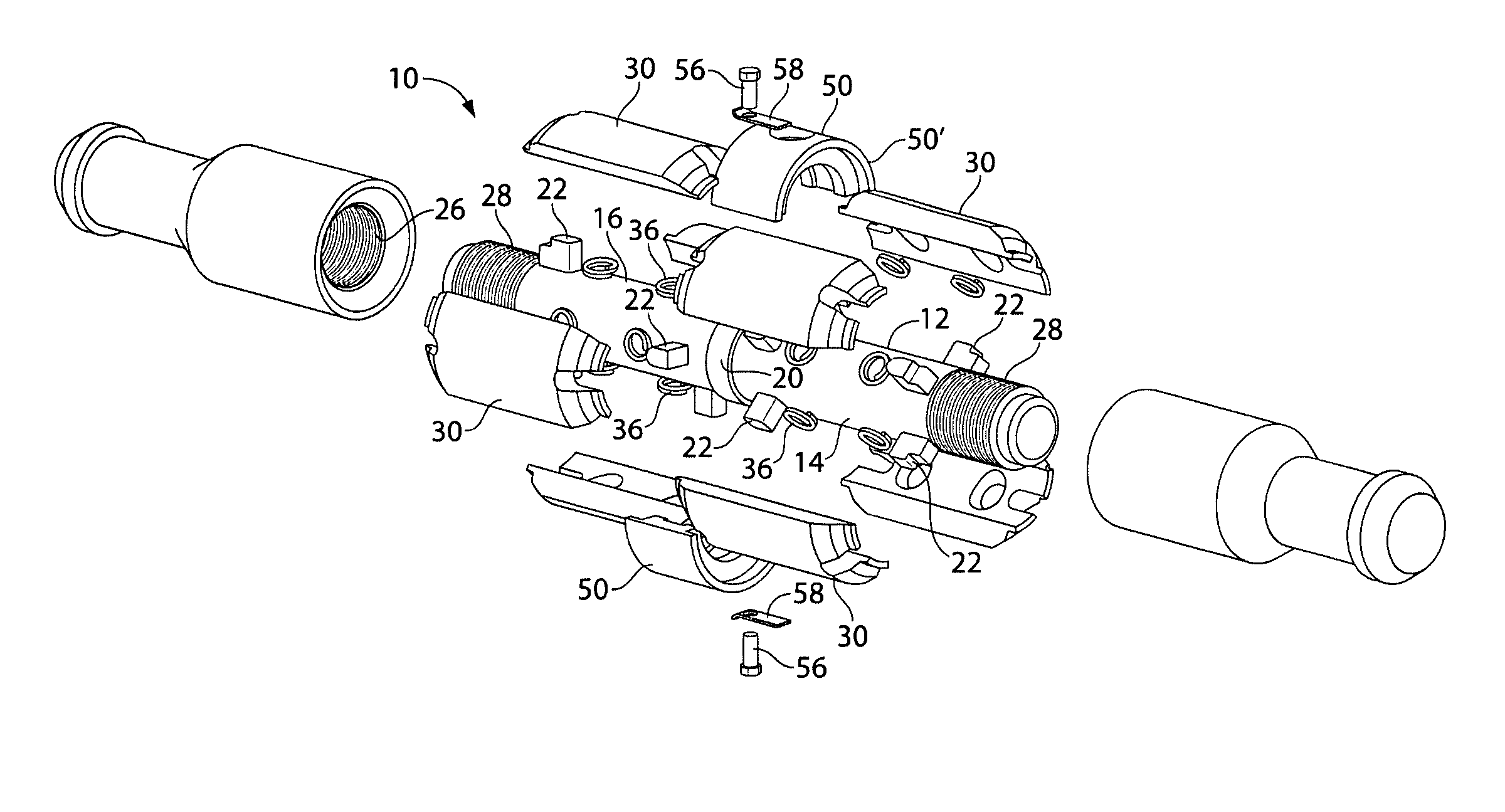
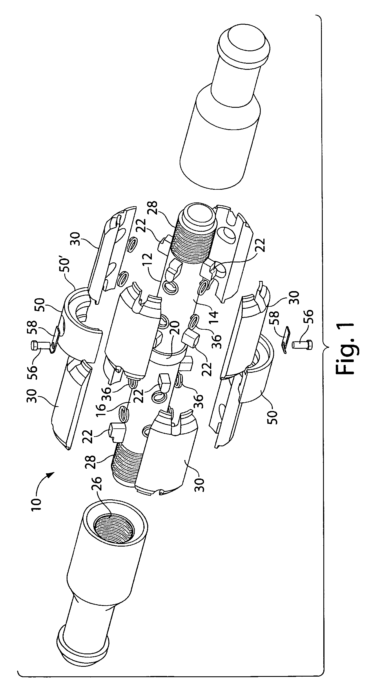
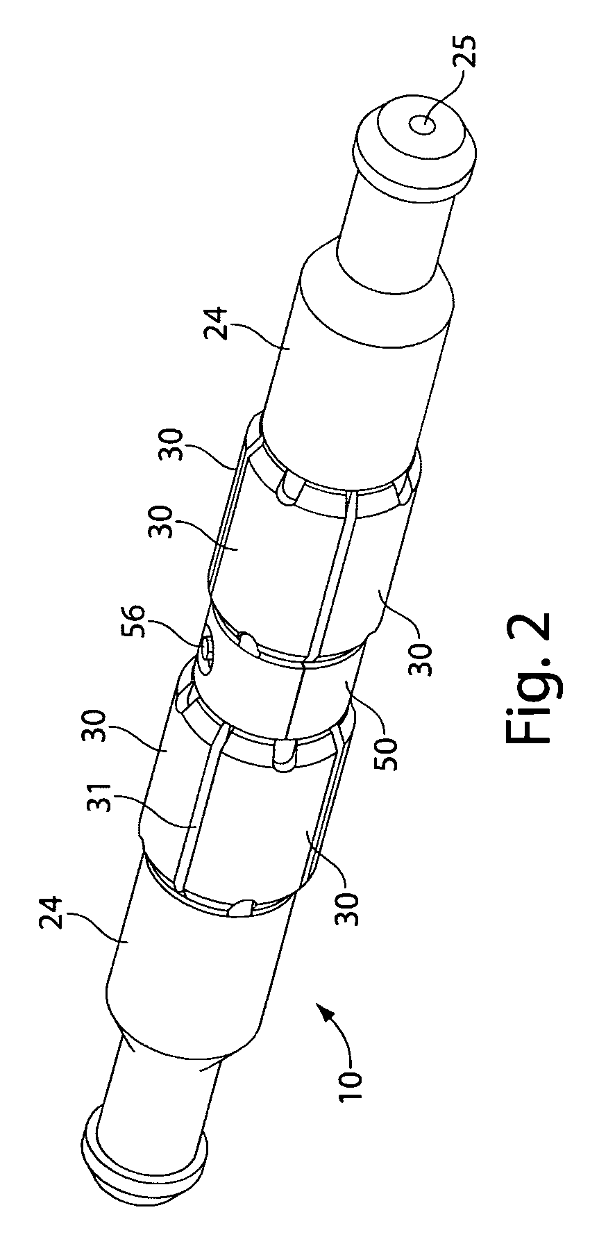
[0028]Referring to the drawings in detail, and particularly to FIG. 1, there is shown in an “exploded” view, the present invention which comprises a split-pad plunger assembly 10 for use in wells, particularly those wells producing natural gas as the primary hydrocarbon. The split-pad plunger assembly 10 of the present invention, shown in an assembled embodiment in FIG. 2, is utilized to cyclically travel between the top of the well to the bottom of the well and back, to drive the bulk of the liquid present in its travel conduit, to the surface. The plunger assembly 10 is comprised of an elongated central core or mandrel 12, shown in FIGS. 1 and 3. The elongated core or mandrel 12 consists of an elongated first half 14 and an elongated second half 16. Each half 14 and 16 at least in this preferred embodiment, is preferably the duplicate of the other half 16 and 14.

[0029]The elongated mandrel 12 has a mid-portion 18 with an annular circumferential securement ring ridge 20 disposed ce...


PUM

PropertyMeasurementUnit
spring strengthaaaaaaaaaa
stiffness-capacityaaaaaaaaaa
pressureaaaaaaaaaa

Abstract

A elongated plunger assembly for pressurized, conduit-enclosed travel utilized in recovery of hydrocarbon deposits in a ground penetrating oil or gas well. The plunger comprises an elongated mandrel, a plurality of radially movable curvilinear wear pads circumferentially disposed adjacent each end of the elongated mandrel, a pad-edge retaining housing extending on at least one end of the elongated mandrel to enclosably retain the longitudinally distal end of a circumferential array of wear pads onto the mandrel, and a centrally disposed wear pad securement ring arrangement to permit release of a worn wear pad, replacement of the worn wear pad at an inner longitudinal edge thereof, thus to permit simple field-accessable removal and replacement of any particular “conduit-worn”“wear” pad from the mandrel of the plunger.

Description

BACKGROUND OF THE INVENTION[0001]1. Field of the Invention[0002]This present invention relates to plunger lift systems for oil and gas wells, and more particularly to a gas lift plunger with an improved assembly arrangement, and is re-filing of Ser. No. 12 / 313,279, and is a continuation-in-part application of Ser. No. 11 / 715,216 filed on Mar. 7, 2007 now U.S. Pat. No. 7,748,448 and also of Ser. No. 12 / 217,756 filed on Jul. 8, 2008 now U.S. Pat. No. 7,793,728, which is a continuation of Ser. No. 11 / 350,367 filed on Feb. 8, 2006, now U.S. Pat. No. 7,395,865 which was based upon Provisional Patent Application 60 / 593,914, filed 24 Feb. 2005, each of which is incorporated herein by reference in its entirety.[0003]2. Background Art[0004]Plunger lift systems are artificial lift systems for use in oil and gas wells. U.S. Pat. No. 6,200,103 to Bender, incorporated herein by reference, discloses a gas lift plunger having a cylindrically elongated plunger body, in which the plunger is utilized...

Claims


Application Information

Patent Timeline
Patent Type & Authority Patents(United States)
IPC IPC(8): E21B17/10E21B23/00E21B33/12
CPCE21B43/121F04B47/12Y10T29/4973
Inventor GREEN, DAVID A.BENDER, ROBERT E.
Owner WELL MASTER CORP
Why Eureka
Try Eureka