Vehicle stability control device

a technology for vehicle stability and control device, which is applied in the direction of control device, vehicle components, vehicle condition input parameters, etc., can solve the problems of reducing confidence in vehicle stability control, unnecessarily activating vehicle stability control, and possibly promoting rear tire wear, so as to reduce the difference in wear degree between the front tire and the rear tire, and promote the effect of rear tire wear

Active Publication Date: 2019-05-30
TOYOTA JIDOSHA KK
View PDF0 Cites 4 Cited by
  • Summary
  • Abstract
  • Description
  • Claims
  • Application Information

AI Technical Summary

Benefits of technology

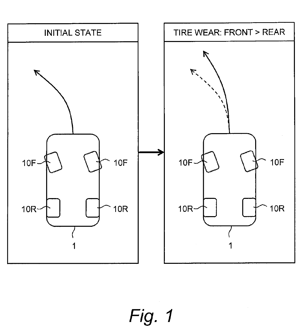
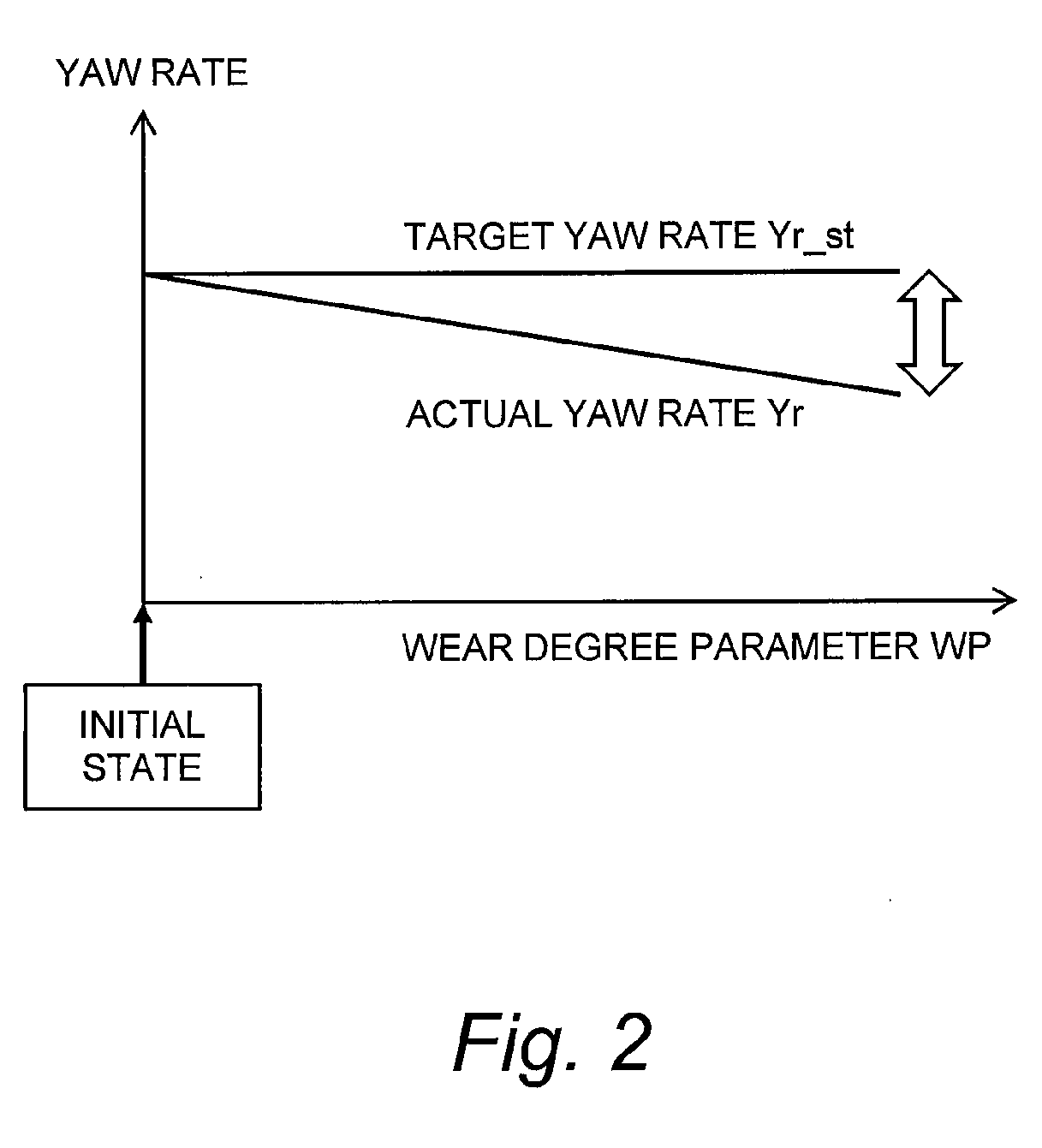
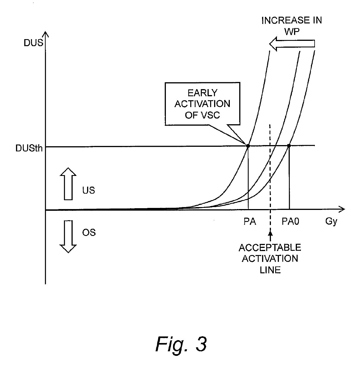
[0038]When the wear degree parameter increases, the calculated target yaw rate deviates from the actual steering characteristic and becomes higher than the actual yaw rate, which causes the unnecessary early activation of the vehicle stability control. According to the present disclosure, in response to a fact that the wear degree parameter exceeds the first wear threshold, the second activation threshold for the rear brake control is changed from the default value to the adjusted value. The adjusted value is smaller than the default value and the first activation threshold for the vehicle stability control. Therefore, a frequency of activation of the rear brake control increases and thus the wear of the rear tire is effectively promoted. When the wear of the rear tire is promoted, a difference in the wear degree between the front tire and the rear tire decreases and thus the wear degree parameter decreases. As a result, the unnecessary early activation of the vehicle stability control is suppressed.

Problems solved by technology

As a result, the vehicle stability control is possibly activated unnecessarily early.
In other words, there is a possibility that the vehicle stability control is activated unnecessarily, although the vehicle stability control is actually unnecessary.
This causes decrease in confidence in the vehicle stability control, which is not preferable.
When the wear degree parameter increases, the calculated target yaw rate deviates from the actual steering characteristic and becomes higher than the actual yaw rate, which causes the unnecessary early activation of the vehicle stability control.
Therefore, a frequency of activation of the rear brake control increases and thus the wear of the rear tire is effectively promoted.

Method used


Image

  • Vehicle stability control device
  • Vehicle stability control device
  • Vehicle stability control device

Examples


first example

5-1. First Example

[0111]In a first example, the wear degree parameter WP is the front wear degree Wf of the front tire 10F. In the case where only the front wear degree Wf is used, an effect of reduction in computation load of the control device 110 can be obtained.

[0112]FIG. 13 is a flow chart showing the first example. The processing flow shown in FIG. 13 is repeatedly executed every certain cycle.

[0113]In the processing flow described below, a parameter F is a status flag indicating whether or not any tire coefficient calculated after initialization exists. When the status flag F is “0”, there is no tire coefficient calculated after the initialization. When the status flag F is “1”, there is any tire coefficient calculated after the initialization. A previous status flag FP indicates a previous value of the status flag F. In the present example, both the status flag F and the previous status flag FP are initialized to “0” in an assembly line of the vehicle 1. Moreover, at timings...

second example

5-2. Second Example

[0126]In a second example, the wear degree parameter WP is the difference (Wf−Wr) between the front wear degree Wf and the rear wear degree Wr. By using both the front wear degree Wf and the rear wear degree Wr, it is possible to more accurately consider the influence of the tire wear.

[0127]FIG. 14 is a flow chart showing the second example. It should be noted that the same Step number is given to the same or similar processing as in the first example, and an overlapping description will be omitted as appropriate.

[0128]In Step S100, the control device 110 calculates the front tire coefficient Kf and the rear tire coefficient Kr and retains them in the memory device 120. More specifically, in Step S110, the control device 110 calculates the vehicle acceleration A(T), the slip ratio Sf(T) of the front tire 10F, and the slip ratio Sr(T) of the rear tire 10R. In Step S120, the control device 110 determines whether or not both the slip ratio Sf(T) and the slip ratio Sr...

third example

5-3. Third Example

[0132]In a third example, the wear degree is calculated based on an “estimated tire radius Ra” instead of the above-described “tire coefficient”. The estimated tire radius Ra is an estimated value of a tire radius and can be obtained, for example, by a method disclosed in the above-mentioned Patent Literature 2 (Japanese Laid-Open Patent Publication No. 2008-247126).

[0133]FIG. 15 is a flow chart showing the third example. It should be noted that the same Step number is given to the same or similar processing as in the first example, and an overlapping description will be omitted as appropriate.

[0134]In Step S100, the control device 110 obtains the estimated tire radius Ra and retains it in the memory device 120. More specifically, in Step S180, the control device 110 determines whether or not the estimation processing is permitted. When the estimation processing is not permitted (Step S180; No), the processing in the current cycle ends. When the estimation processi...


PUM


Abstract

A vehicle stability control device is mounted on a vehicle in which a front tire wears faster than a rear tire. Understeer degree increases as a target yaw rate becomes higher than an actual yaw rate. When the understeer degree exceeds a first activation threshold, vehicle stability control is activated. When the understeer degree exceeds a second activation threshold, rear brake control that applies a braking force to an inner rear wheel is activated. A wear degree parameter is wear degree of the front tire or a difference in wear degree between the front tire and the rear tire. In response to a fact that the wear degree parameter exceeds a first wear threshold, the vehicle stability control device performs rear wear promotion processing that changes the second activation threshold to an adjusted value smaller than a default value and the first activation threshold.

Description

BACKGROUNDTechnical Field[0001]The present disclosure relates to a vehicle stability control device that performs vehicle stability control in consideration of tire wear.Background Art[0002]Vehicle stability control is a function to suppress sideslip and spin to stabilize vehicle behavior during a turn of a vehicle. More specifically, a target yaw rate is calculated according to a vehicle speed and a steering angle. Meanwhile, an actual yaw rate is detected by a yaw rate sensor. An understeer tendency or an oversteer tendency is detected based on a deviation between the target yaw rate and the actual yaw rate. When the understeer tendency or the oversteer tendency exceeds a certain level, the vehicle stability control is activated. In the vehicle stability control, a braking force and / or a driving force of each wheel is appropriately controlled in order to stabilize the vehicle behavior.[0003]Patent Literature 1 discloses a wear state detection device that detects a wear state of a ...

Claims


Application Information

Patent Timeline
Patent Type & Authority Applications(United States)
IPC IPC(8): B60W30/02B60W40/114B60W30/18
CPCB60W30/02B60W40/114B60W30/18145B60W2520/14B60W2710/18B60W2530/20B60W30/045B60W2520/10B60W2520/26B60W2520/105
Inventor WATANABE, RYOCHI
Owner TOYOTA JIDOSHA KK
Why Eureka
Try Eureka