Eureka AIR delivers breakthrough ideas for toughest innovation challenges, trusted by R&D personnel around the world.

Mobile lighting system

a portable lighting and lighting technology, applied in outdoor lighting, protective devices for lighting, outdoor lighting, etc., can solve the problems of unsatisfactory lighting, inflatable balloon envelopes tend to deform quite readily, illuminated balloons switching off more, etc., to reduce the noise of the fan, increase the pressure setting, and reduce the speed of the fan

Inactive Publication Date: 2007-07-24
LUNAR LIGHTING
View PDF19 Cites 16 Cited by
  • Summary
  • Abstract
  • Description
  • Claims
  • Application Information

AI Technical Summary

Benefits of technology

[0016]The legs make the trailer more stable and able to cope with any horizontal wind loads which the apparatus may be subjected to.
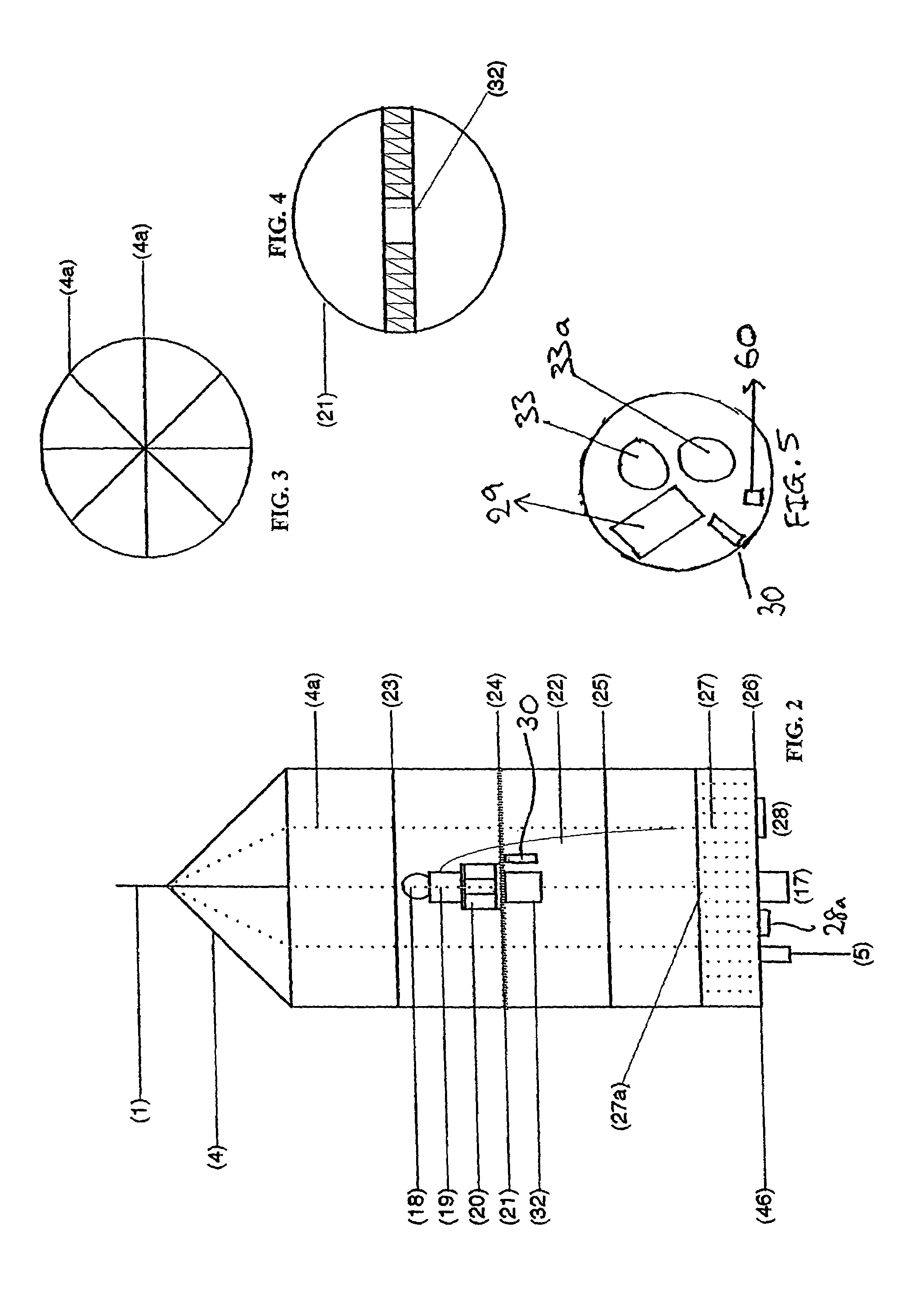
[0021]The envelope is preferably made of a polymer most preferably a clear acrylic or polycarbonate. Typically the envelope is formed by slump moulding two sheets of clear acrylic into dome shapes and joining the two deformed sheets to form an ellipsoid. The interior surface of the upper dome is preferably coated with a UV resistant silver reflective polyurethane spray paint and the lower dome is treated to provide diffused light by frosting the acrylic (by sandblasting or the like). Alternatively the lower dome is coated with a UV resistant manufactured textile to act as a diffuser and provide glare free light.
[0027]The balloon preferably also incorporates two variable speed fans so the fans can be set at low speed when the apparatus is required to operate quietly as is required for filming. When the fan runs at low speed the variable pressure gauge can be set to tolerate larger drops in pressure to prevent safety cut-out due to the low fan speed.
[0028]By reducing the fan speed and increasing the pressure setting on the pressure sensor, the noise of the fan can be dramatically reduced.
[0029]In one embodiment a cover, typically made from polycarbonate lined with a sound absorbing material, may be placed over the base plate. The cover defines two air intake apertures and quietens the fans without compromising the pressure inside the inflatable envelope. This is important when the apparatus is used out doors especially in windy conditions where the balloon needs to be firm enough to withstand horizontal wind loads.
[0031]In a preferred feature, two mini compressors can be used to inflate the balloon, thereby halving the inflation time. Once the balloon is inflated, the pressure created inside the envelope is sufficient to stop the safety sensors from cutting power to the bulb in high wind conditions.

Problems solved by technology

However, there are a number of problems with such balloons.
Inflatable balloon envelopes tend to deform quite readily when subject to relatively strong air currents because of the relatively low pressure setting and even the smallest holes in the envelope may cause the safety circuit to cut power to the bulb.
In more adverse conditions, illuminated balloons switch off more often and provide unsatisfactory lighting.
The prior art deflection systems are typically mechanical systems such as the filar elements of U.S. Pat. No. 5,782,668 and are unreliable, over-sensitive and difficult to adjust.
This method is awkward to use and is not well suited to many applications, particularly when reliable and quick anchoring of the balloons is required.
A second problem with existing conventional lighting towers is that a very heavy base is required.
There is a third problem with existing inflatable balloon systems and that is their slow inflation rate and noisy operation which is a particular problem when filming.

Method used


Image

  • Mobile lighting system
  • Mobile lighting system
  • Mobile lighting system

Examples


Embodiment Construction

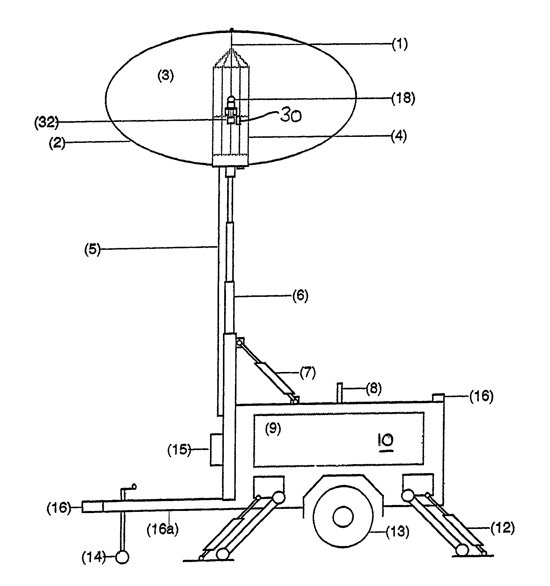
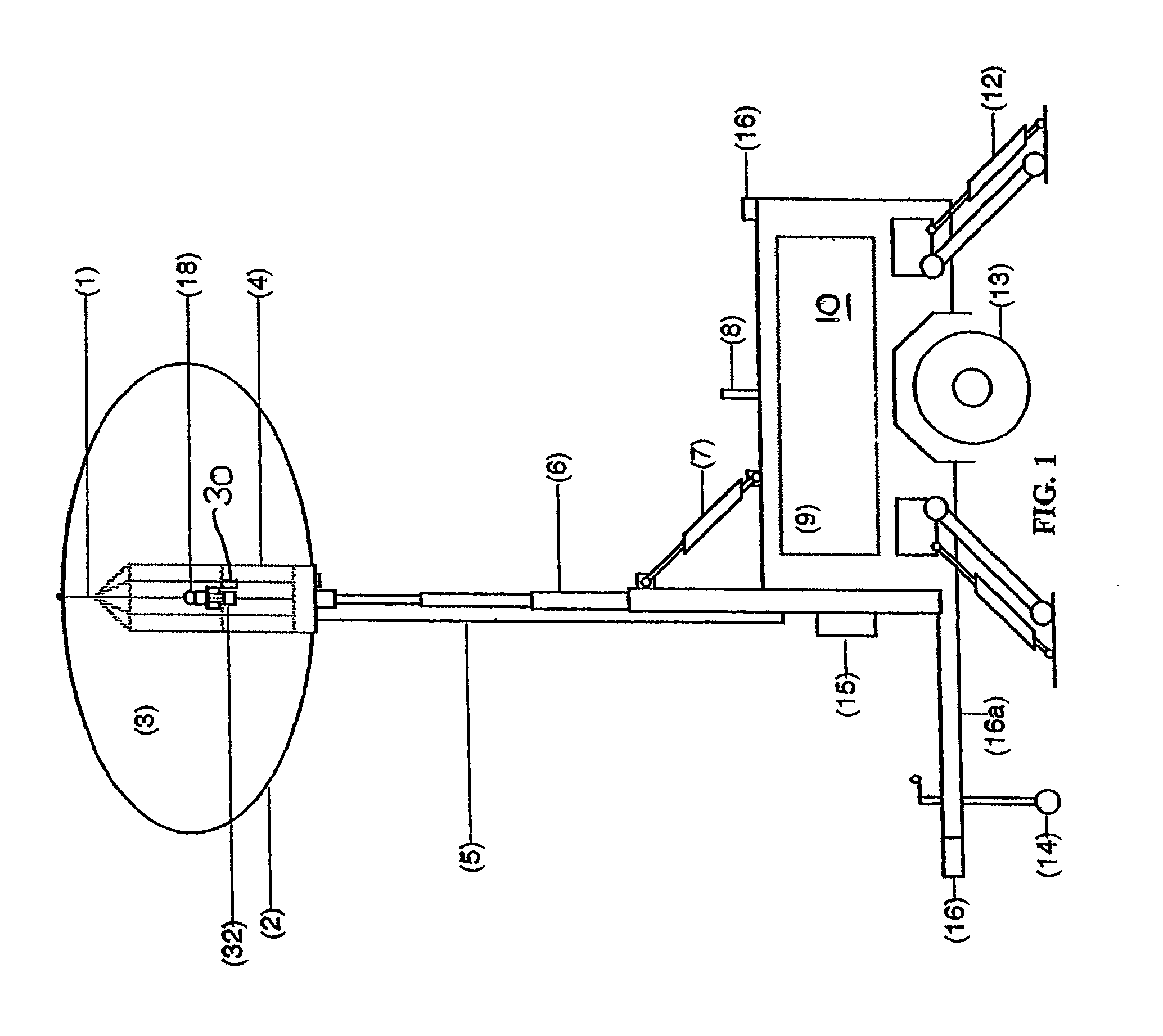
[0044]With reference to the drawings, FIG. 1 shows a portable lighting system generally including an inflatable envelope or balloon 2. Inside the balloon there is located an aluminium support frame or cage 4 from the top of which one aluminium rod 1 extends to make an oval envelope / balloon. Two such rods 1 joined end on end can be used to increase the height of the balloon to make it generally spherical. A light head 3 is located inside the cage.

[0045]The inflatable balloon 2 and the support frame 4 are mounted on one end of a mast 6 which has four telescopically slidable sections and is ten metres tall when fully extended. The mast is mounted on a trailer 16. A hydraulic ram 7 extends between the lowermost section of the mast 6 and the top of the trailer 16 for use in lifting the mast into a vertical upright position as shown in FIG. 1. The mast can be retracted and folded onto the top of the trailer when not in use.

[0046]The trailer 16 includes a tow bar 16a jockey wheel 14 and a ...


PUM


Abstract

A portable lighting apparatus includes an envelope which contains a frame supporting an illuminating device typically an electric light bulb inside the envelope. The envelope is mounted on a telescopic mast supported by a movable base element incorporating stabilising legs. The envelope may be inflatable or rigid. For an inflatable envelope, various sensors are provided for sensing deformation of the envelope and / or pressure in the envelope including a photosensor. A means to supply air or other gas to inflate the envelope are provided. A rigid envelope formed from two conjoined sheets of acrylic deformed into dome shapes is also disclosed which overcomes many of the problems of inflatable envelopes particularly, their slow inflation rate, the tendency to deform due to air currents and the adverse effect of punctures. Although a fan is not required for inflation of the rigid envelope fan forced air is preferred for cooling the electric light bulb.

Description

CROSS REFERENCE TO RELATED APPLICATIONS[0001]This application claims priority to PCT / AU03 / 00599 filed May 19, 2003.FIELD OF THE INVENTION[0002]This invention relates to an improved portable lighting system as well as to a new permanent or portable lighting system. In particular, the invention relates to an illuminating balloon which includes an envelope. The envelope contains an illuminating device incorporating an electric bulb or the like and means for keeping the envelope inflated, typically using air, and for supplying power to the light bulb.BACKGROUND OF THE INVENTION[0003]It is known to provide a balloon comprising an inflatable envelope which is inflated with a gas such as air or helium, place a light source in the balloon and tether the balloon to the ground using an elongate element keeping the balloon at a certain height above the ground. Such balloons are used either for decoration, for carrying advertisements where the envelope or fabric of the balloon carries such an a...

Claims


Application Information

Patent Timeline
Patent Type & Authority Patents(United States)
IPC IPC(8): F21V33/00F21L14/04F21S8/00F21V3/00F21V21/22F21V29/02G09F21/06
CPCB60P3/18F21L14/04F21V3/023F21V21/22F21V29/02G09F21/06F21W2131/10F21V29/67F21V29/60
Inventor OSSOLINSKI, GEORGE
Owner LUNAR LIGHTING
Why Eureka
Eureka Blog
Learn More