Obstacle detection using stereo vision

a stereo vision and obstacle detection technology, applied in adaptive control, television systems, instruments, etc., can solve problems such as the inability of monocular machine vision to support obstacle detection, and the inability of monocular machine vision to provide reliable obstacle identification

Active Publication Date: 2007-07-24
DEERE & CO
View PDF19 Cites 99 Cited by
  • Summary
  • Abstract
  • Description
  • Claims
  • Application Information

AI Technical Summary

Problems solved by technology

Monocular machine vision may offer limited capability in supporting obstacle detection for vehicles.
However, monocular vision data may be deficient in providing reliable identification of obstacles based on size, shape, depth, and other three dimensional geometric characteristics.
Monocular machine vision tends to be over-inclusive or under-inclusive in obstacle identification because of the absence of three-dimensional data on the size and shape of a perceived obstacle.
Further, the collection of monocular vision data is susceptible to distortion or inaccuracy arising from variations in illumination across a field of view.
Although three-dimensional shape data of an object may be collected via a laser range finder that scans the surface of the object, the process may be too slow to be practical for vehicular navigation.

Method used


Image

  • Obstacle detection using stereo vision
  • Obstacle detection using stereo vision
  • Obstacle detection using stereo vision

Examples


Embodiment Construction

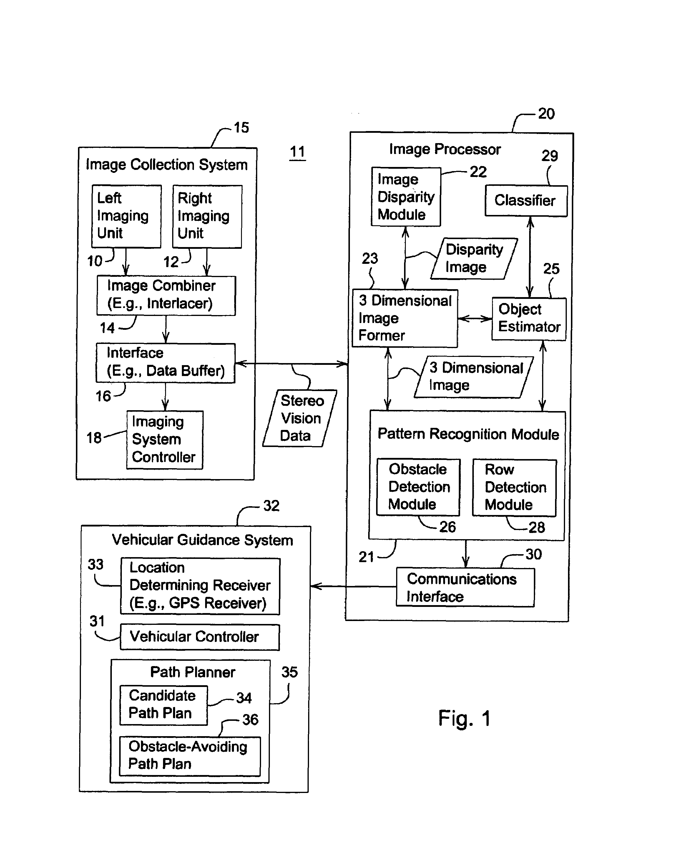
[0017]In accordance with one embodiment, FIG. 1 illustrates a detection system 11 for detecting an obstacle in a field of view around a vehicle. The detection system 11 comprises an image collection system 15 coupled to an image processor 20. In turn, the image processor 20 is coupled to a vehicular guidance system 32.

Image Collection System

[0018]The image collection system 15 comprises a left imaging unit 10 and a right imaging unit 12 that are coupled to an image combiner 14 (e.g., an interlacer). The image combiner 14 may be coupled to an interface 16. The interface 16 provides a communications interface (or a data buffer) for the stereo vision data transmitted from the image collection system to the image processor 20. An imaging system controller 18 may control the optical characteristics of the left imaging unit 10, the right imaging unit 12, or the format of stereo vision data or image data outputted by the interface 16, for example.

[0019]The optical characteristics of the im...


PUM


Abstract

A system and method for detecting an obstacle comprises determining a vegetation height of a vegetation canopy at corresponding coordinates within a field. An object height is detected, where the object height of an object exceeds the vegetation height. A range of the object is estimated. The range of the object may be references to a vehicle location, a reference location, or absolute coordinates. Dimensions associated with the object are estimated. An obstacle avoidance zone is established for the vehicle based on the estimated range and dimensions.

Description

FIELD OF THE INVENTION[0001]This application relates to a system and method for obstacle detection using stereo vision.BACKGROUND OF THE INVENTION[0002]Monocular machine vision may offer limited capability in supporting obstacle detection for vehicles. An obstacle may be detected by identifying a monocular image feature that violates expected scene information. For example, monocular vision data may be used to potentially identify objects in a field that do not meet a soil image profile or a plant image profile as an obstacle. However, monocular vision data may be deficient in providing reliable identification of obstacles based on size, shape, depth, and other three dimensional geometric characteristics. Monocular machine vision tends to be over-inclusive or under-inclusive in obstacle identification because of the absence of three-dimensional data on the size and shape of a perceived obstacle. Further, the collection of monocular vision data is susceptible to distortion or inaccur...

Claims


Application Information

Patent Timeline
Patent Type & Authority Patents(United States)
IPC IPC(8): G06K9/20G05B13/00
CPCG01S11/12G06K9/00664G06K9/00697G06V20/38G06V20/10G06V20/188
Inventor REID, JOHN FRANKLIN
Owner DEERE & CO
Why Eureka
Try Eureka