Primary side current balancing scheme for multiple CCF lamp operation

a current balancing and lamp operation technology, applied in the field of current balancing, can solve the problems of reducing electronic control and power switching devices, system cost, and difficulty in achieving equal current sharing among lamps, and achieve the effect of balancing mechanisms

Inactive Publication Date: 2007-07-31
MICROSEMI CORP
View PDF182 Cites 25 Cited by
  • Summary
  • Abstract
  • Description
  • Claims
  • Application Information

AI Technical Summary

Benefits of technology

[0014]In one application, two transformer groups are coupled in parallel to a common power source via a balancing transformer. The balancing transformer has a first balance winding coupled in a first polarity between the common power source and the first transformer group and a second balance winding coupled in a second polarity between the common power source and the second transformer group. The first polarity and the second polarity are opposite polarities. Coupling the balance windings in opposite (or reverse) polarities between the common power source and the respective transformer groups results in substantially no voltage drop across the balance windings due to magnetic flux when both balance windings are conducting substantially identical currents. Imbalances between the currents conducted by the balance windings generate magnetic flux in the core of the balancing transformer. The magnetic flux induces corresponding voltages across the balance windings which are in anti-phase relationship to correct the current imbalance.

Problems solved by technology

One of the challenges to a multiple lamp operation is how to maintain substantially equal or controlled operating currents for the respective lamps, thereby yielding the desired illumination effect on the display screen, while reducing electronic control and power switching devices to reduce system cost.
When multiple lamps are connected in parallel across a common voltage source, equal current sharing among the lamps is difficult to achieve without a current balancing mechanism.
In constructing a display panel with multiple lamps, it is difficult to provide identical surrounding conditions for each lamp.
A limitation of the above approach occurs when the number of lamps, and consequently the number of transformers, increases.
The design of the associated transformers becomes difficult.

Method used


Image

  • Primary side current balancing scheme for multiple CCF lamp operation
  • Primary side current balancing scheme for multiple CCF lamp operation
  • Primary side current balancing scheme for multiple CCF lamp operation

Examples


Embodiment Construction

[0027]Although particular embodiments are described herein, other embodiments, including embodiments that do not provide all of the benefits and features set forth herein, will be apparent to those of ordinary skill in the art.

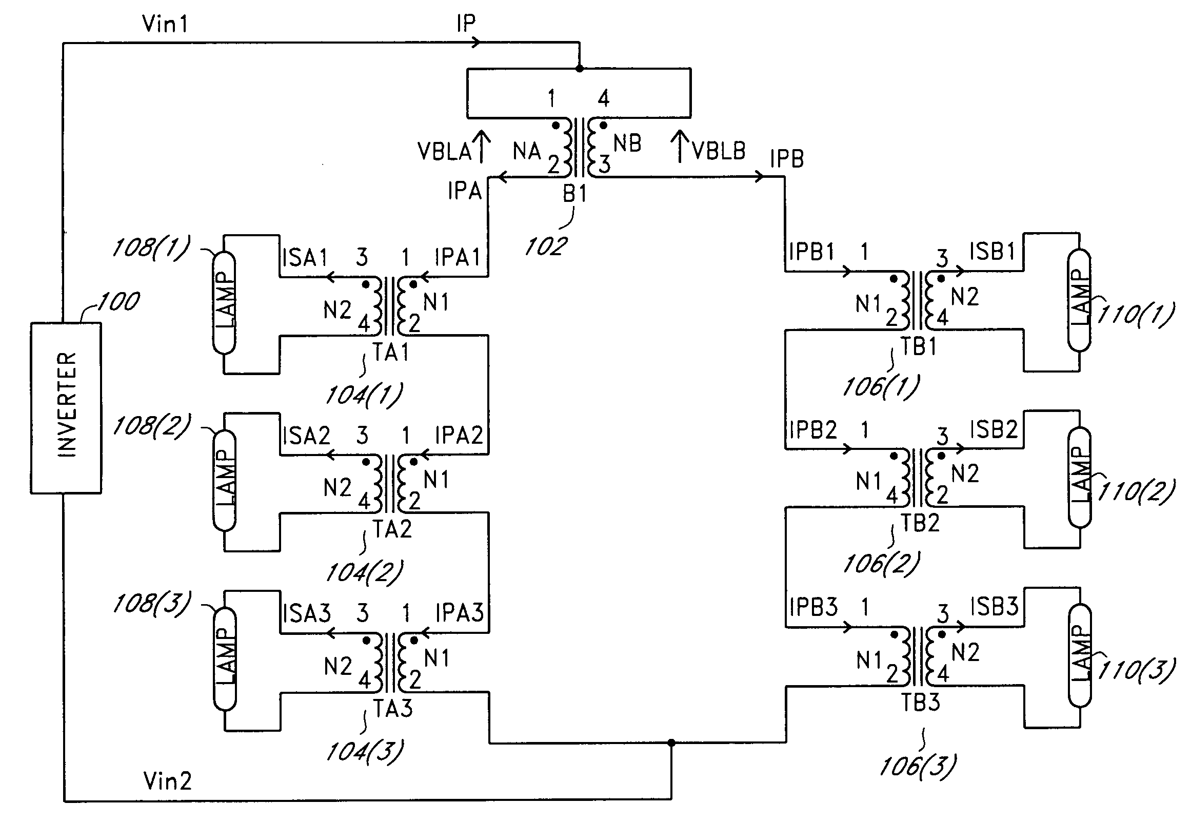
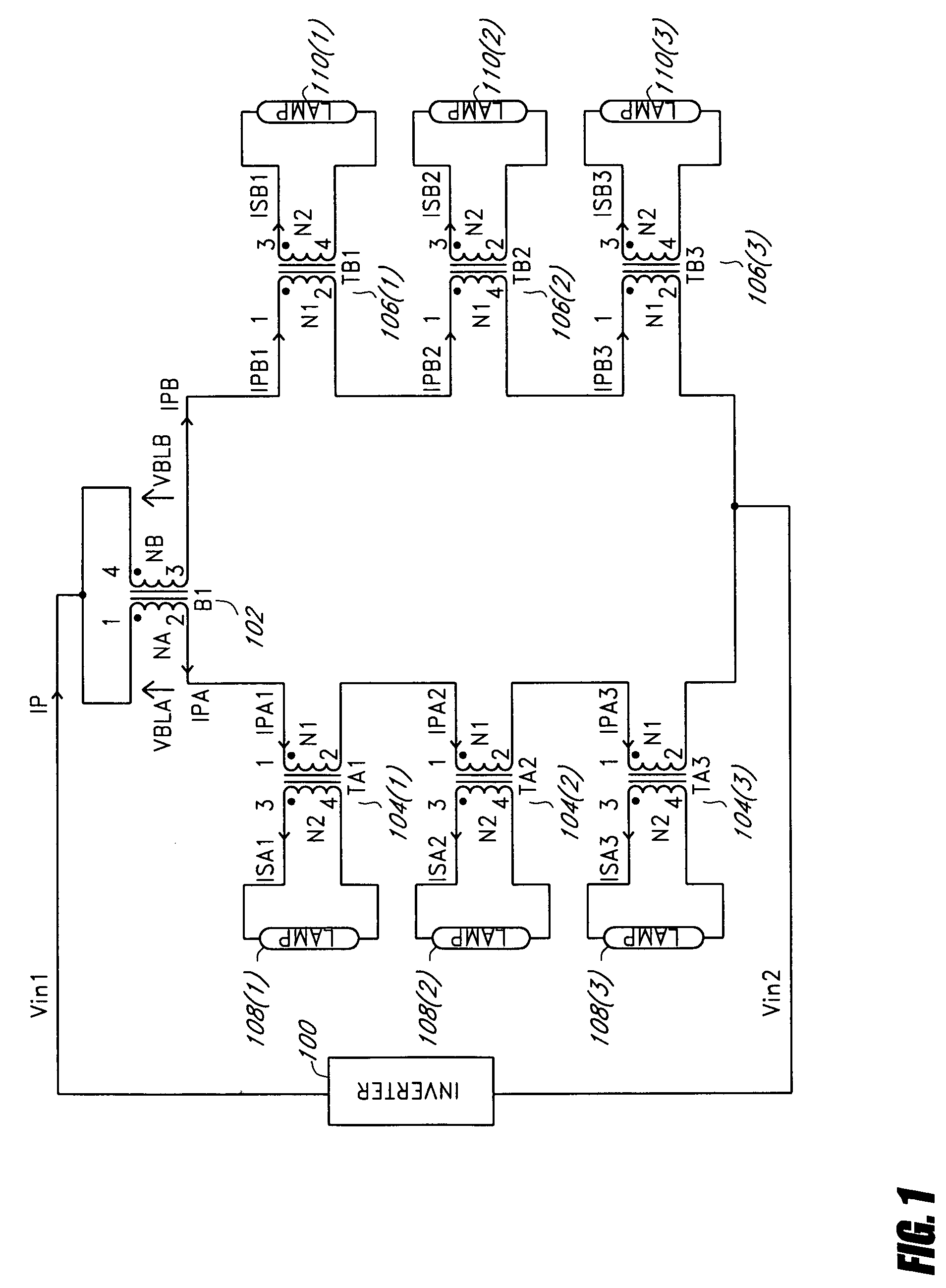
[0028]FIG. 1 illustrates one embodiment of balanced groups of serially-coupled lamp transformers using one balancing transformer (B1) 102 for two transformer groups. The balancing transformer 102 has two balance windings coupled in reverse polarity between an input node (Vin1) and the respective transformer groups. In one embodiment, an inverter 100 is coupled between the input node and a reference node (Vin2) to generate a voltage supply or a current supply. The voltage supply or the current supply provides a common AC current (IP) to the balancing transformer 102. The balancing transformer 102 divides the common AC current into two balanced currents (IPA, IPB). The first balanced current (IPA) is conducted by the first balance winding and the second balanced...


PUM


Abstract

A backlight system drives multiple lamps using balanced groups of serially-connected lamp transformers. A plurality of lamp transformers is divided into multiple transformer groups. Primary windings of the lamp transformers are coupled in series in each transformer group. Lamps are coupled to secondary windings of the lamp transformers. The transformer groups are arranged in a parallel configuration. One or more balancing transformers couple the transformer groups to a common power source. The balancing transformers divide a common current from the common power source into multiple balanced currents for the respective transformer groups.

Description

CLAIM FOR PRIORITY[0001]This application claims the benefit of priority under 35 U.S.C. § 119(e) of U.S. Provisional Application No. 60 / 560,031, filed on Apr. 7, 2004, and entitled “A Primary Side Current Balancing Scheme for Multiple CCF Lamp Operation,” the entirety of which is incorporated herein by reference.BACKGROUND[0002]1. Field of the Invention[0003]The invention generally relates to current balancing and more particularly to using balanced groups of serially-connected transformers to balance current among multiple lamps in a backlight system.[0004]2. Description of the Related Art[0005]In liquid crystal display (LCD) applications, backlight is needed to illuminate the screen to make a visible display. With the increasing size of LCD panels (e.g., LCD television or large screen LCD monitor), cold cathode fluorescent lamp (CCFL) backlight systems may operate with multiple lamps to obtain high quality illumination for a display screen. One of the challenges to a multiple lamp...

Claims


Application Information

Patent Timeline
Patent Type & Authority Patents(United States)
IPC IPC(8): H05B41/16H05B37/02H05B41/282
CPCH05B41/282H05B41/2822Y02B20/183Y02B20/00
Inventor JIN, XIAOPING
Owner MICROSEMI CORP
Why Eureka
Try Eureka