Co-charging system by a solar panel and (AC adaptor or Mobile battery)

a solar panel and solar energy technology, applied in the direction of electric variable regulation, process and machine control, instruments, etc., can solve the problem that the life of lead-acid batteries is only about 3 years

Active Publication Date: 2022-08-11
IWASA HIROSHI
View PDF0 Cites 0 Cited by
  • Summary
  • Abstract
  • Description
  • Claims
  • Application Information

AI Technical Summary

Benefits of technology

[0014]By using the co-charging system of this invention, a 12V battery such as a lead storage battery is not required, so that depreciation cost can be suppressed. In addition, the weight is reduced because there is no heavy lead-acid battery. Regarding the path of direct charging from the solar cell, a DC power supply is performed to charge the charging target without converting it to alternating current from the solar panel even once, and voltage conversion is performed only once, so there is no waste. And since it is featured with a stand-alone mode and has an analog switching element in the solar cell system to provide feedback, it is possible to efficiently charge the device to be charged even when power is supplied only from the solar cell. Then, when the solar cell is not generating power, there is an analog switching element connected in series between the solar cell and the device to be charged with the directions reversed from each other. Therefore, when there is only one solar cell, the power supply system does not require the reverse current protection diode. Therefore, there is no voltage drop due to the reverse current prevention diode, and the power efficiency is good. Further, due to various measures such as a diode, a large-capacity capacitor, and power saving, even if the mobile battery stops supplying power once, charging is started immediately depending on the mobile battery when the device to be charged is connected.

Problems solved by technology

However, the storage battery used in a normal independent power supply system is a consumable item, and can be used for only about 3 years in a short case under normal usage.
However, in the short case, the lead-acid battery lasts only about 3 years.

Method used


Image

  • Co-charging system by a solar panel and (AC adaptor or Mobile battery)
  • Co-charging system by a solar panel and (AC adaptor or Mobile battery)
  • Co-charging system by a solar panel and (AC adaptor or Mobile battery)

Examples


Embodiment Construction

[0026]The first embodiment relates to a cooperative charging system.

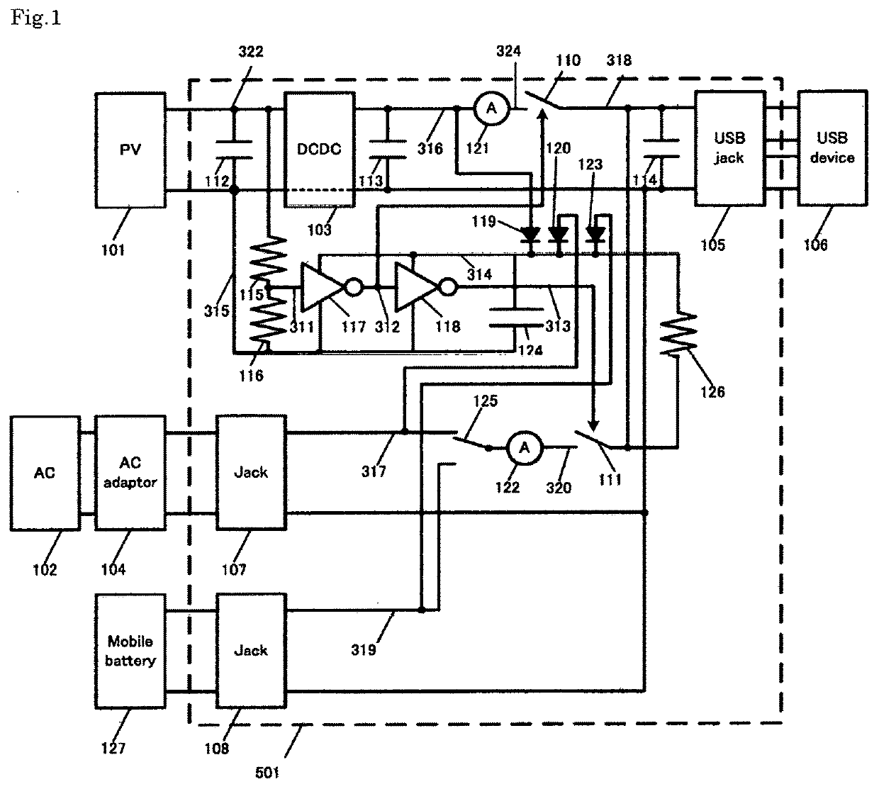
[0027]FIG. 1 shows a diagram of a cooperative charging system according to the first embodiment. The cooperative charging system includes a control circuit 501, a solar panel 101, a commercial AC power supply 102, an AC adapter 104, a mobile battery 127, and a USB device (charge target device) 106.

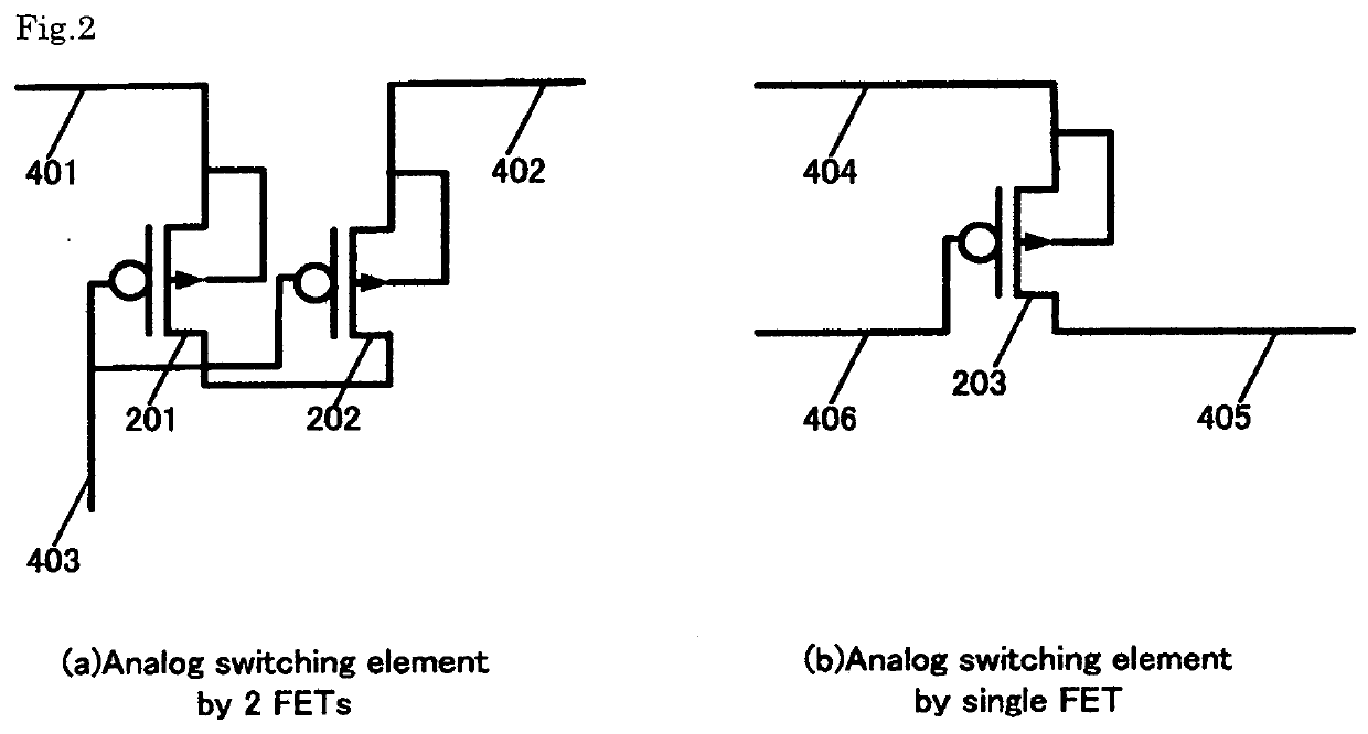
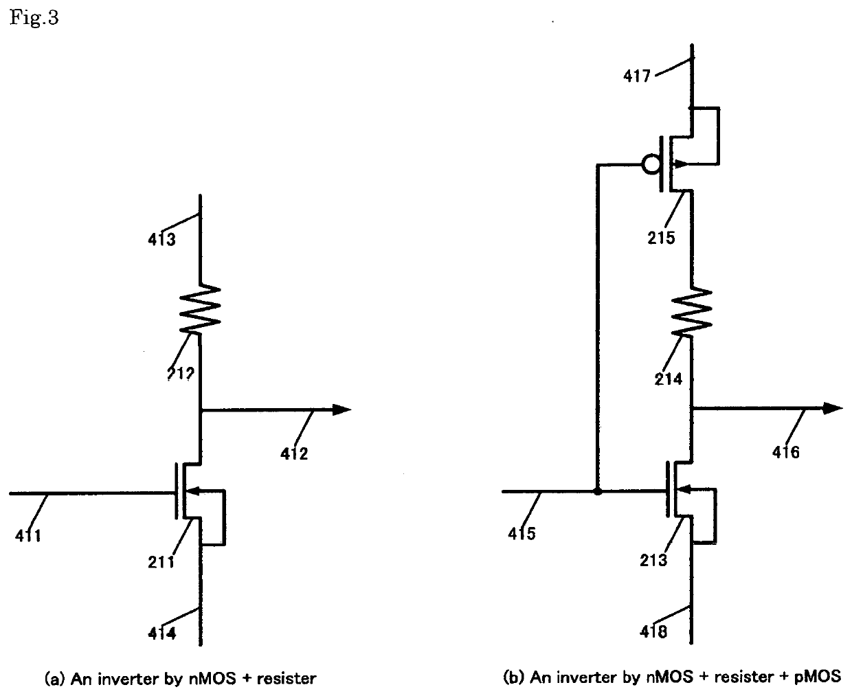
[0028]The control circuit 501 includes a DC / DC converter 103, a USB jack 105, analog switching elements 110, 111, capacitors 112, 113, 114, resistors 115, 116, inverters 117, 118, and rectifying diodes 119, 120, 123, current meters 121 and 122, a large-capacity capacitor 124, a mechanical switch 125, and a resistor 126.

[0029]The connection will be described with respect to the control circuit 501 and its peripheral parts. The positive terminal of the solar panel 101 is connected to the positive input terminal of the DC-DC converter 103, the positive terminal of the capacitor 112, and one end of the resistor 115. The negati...


PUM


Abstract

PROBLEM TO BE SOLVED: To provide a charging system which does not require a 12V storage battery and suppresses depreciation cost.HOW TO SOLVE: In a co-charging system, if charging is possible through two routes which are “through selected one by a mechanical switch 125 of (a commercial AC power supply 102 and AC adapter 104,) or a mobile battery 127”, and “through solar cell 101 and a DC / DC converter 103”, a circuit 501 charges the USB device 106 in cooperation with the two routes. The USB device 106 is charged efficiently from the solar cell 101 by reducing the current even if the power is not supplied by (one selected by the switch 125 from “the commercial AC power supply 102 and the AC adapter 104”, or “the mobile battery 127”). Further, even if the mobile battery stops supplying power once, when the USB device 106 is connected again, the mobile battery immediately starts charging.

Description

CROSS-REFERENCE TO RELATED APPLICATION[0001]The present application claims the benefit application number 2020-196435, filed in Japan on Nov. 27, 2020, the subject matter of which is hereby incorporated herein by reference.STATEMENT REGARDING FEDERALLY SPONSORED RESEARCH OR DEVELOPMENT[0002]The inventor is not sponsored by federal government.REFERENCE TO A “SEQUENCE LISTING,” A TABLE, OR A COMPUTER PROGRAM LISTING APPENDIX SUBMITTED ON A COMPACT DISC AND AN INCORPORATION-BY-REFERENCE OF THE MATERIAL ON THE COMPACT DISC[0003]N / ABACKGROUND OF THE INVENTION[0004]This invention relates to a system for cooperatively charging a target device by electric power from a plurality of electric power sources such as a solar cell and an AC adapter, or a solar cell and a mobile battery.[0005]In recent years, photovoltaic power generation has been attracting attention. The photovoltaic power generation system includes an independent power supply system and a grid linkage system. The former stores e...

Claims


Application Information

Patent Timeline
Patent Type & Authority Applications(United States)
IPC IPC(8): H02J7/35H02M3/156H02M7/537
CPCH02J7/35H02J2207/20H02M7/537H02M3/156Y02B10/10H02M1/0006H02M1/10H02M1/36H02M1/15H02M1/32H02J7/02H02J2207/40H02J2207/30H02J1/084
Inventor IWASA, HIROSHI
Owner IWASA HIROSHI
Why Eureka
Try Eureka