Air purifier

a technology of air purifier and air stream, which is applied in the field of air purifier, can solve the problems of not being able to create an ionized cloud outside of the device capable of generating sufficient static electricity to cause electrostatic discharge and shock an individual near the device, and achieve the effects of effective charging of particulates in the air stream, maximizing ion generation, and maximizing the flow of ions through the devi

Inactive Publication Date: 2007-02-15
SC JOHNSON & SON INC
View PDF99 Cites 79 Cited by
  • Summary
  • Abstract
  • Description
  • Claims
  • Application Information

AI Technical Summary

Benefits of technology

[0012] According to a first aspect of the present invention, an air purifier is provided in which air is passed through the purifier from an air inlet to an air outlet. Air from the environment to be purified is drawn into the inlet of the device by a fan which can be located within the device at almost any point along the flow path for the device. The air entering the device through the inlet passes an upstream ionizer that effectively charges the particulates in the air stream by emitting ions that attach to the particulates flowing past the ionizer. The ionized particles are then entrapped by a filter element disposed downstream of the ionizer that is manufactured to have a charge opposite to that of the ions generated by the ionizer. Due to the attraction between the charged particles and the oppositely charged filter, the charged particulates are entrapped within the filter and removed from the air, which passes through the filter and out of the device. The ionizer is configured with an ionizing needle from which the ions that adhere to the particulates are generated, and a ground plate spaced from the ionizing needle. The ground plate functions to restrict the dispersion of ions from the ionizing needle in a manner which focuses the dispersion of ions from the ionizing needle along the flow path for the air through the device. In other words, the ions generated by the ionizing needle are essentially contained within the device, and cannot create an ionized cloud outside of the device capable of generating sufficient static electricity to cause an electrostatic discharge and shock an individual near the device. Further, the ionizing needle is shaped to have as sharp a profile as possible in order to maximize the ion generation from the point of the ionizing needle or pin, in order to maximize the flow of ions through the device. This configuration for the ionizing pin also assists the ground plate in directing the ions through the device.
[0013] According to another aspect of the present invention, the device may include a downstream ionizer, in addition to, or without the upstream ionizer. The downstream ionizer is positioned adjacent the outlet end of the device and is constructed similarly to the upstream ionizer with an ionizing pin and a ground plate. The pin can be oriented to point oppositely to or in the same direction as the air flow path through the device, and functions to charge the particulates in the air passing the pin. The ground plate operates to ensure that the ions formed by the pin are contained within the device to substantially reduce any electrostatic discharge problems. However, because the downstream ionizer is located downstream from the filter, the particles charged by the ions from the ionizer pin are directed out of the outlet for the device by the fan. Due to their charged state, these particles are attracted to various oppositely charged surfaces in the room, such as tables, floors, etc., where the particulates come to rest. The particulates can then be cleaned from these surfaces.
[0014] According to still another aspect of the present invention, the device includes a housing for the charged filter element that acts as a lockout feature for the device in order to insure that the filter and housing are positioned within the device prior to activation of the device. By insuring that the oppositely charged filter is located within the flow path through the device prior to activation of the upstream ionizer, the ions generated by the upstream ionizer are effectively maintained within the device as the majority of the ions are entrapped by the oppositely-charged filter, maintaining the ions within the device to avoid any electrostatic discharge outside of the device.
[0016] According to still another aspect of the present invention, the air flow path through the device is designed to create a substantially laminar flow for the air drawn into the device and increase the efficiency of the device. This is achieved by the configuration of the interior flow pathway within the device, in order to create the desired angles for air flow into and out of the device. This substantially laminar flow is accomplished by the structure of the housing of the device and optionally a baffle positioned within the housing, which functions to draw air to be cleaned into and direct the air out of the device at an angle of approximately 45°, in conjunction with the baffle or baffles positioned within the device.

Problems solved by technology

In other words, the ions generated by the ionizing needle are essentially contained within the device, and cannot create an ionized cloud outside of the device capable of generating sufficient static electricity to cause an electrostatic discharge and shock an individual near the device.

Method used


Image

  • Air purifier
  • Air purifier
  • Air purifier

Examples


second embodiment

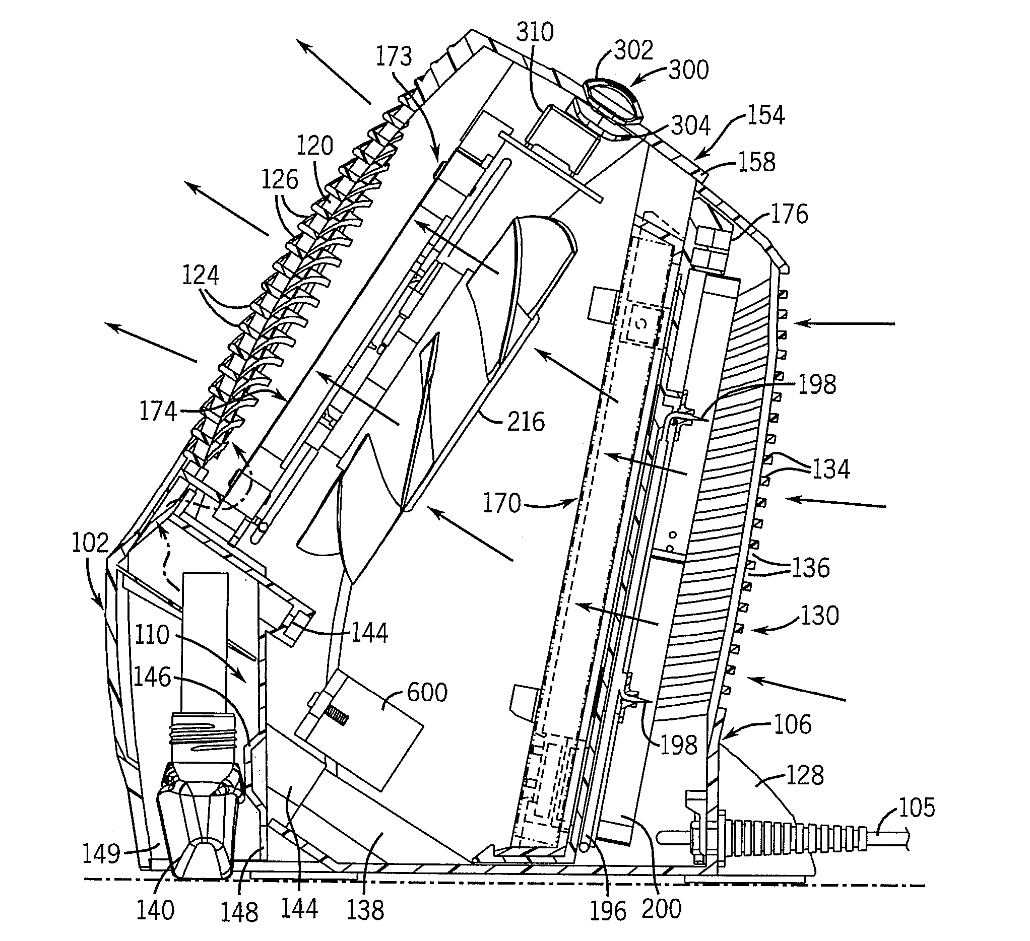
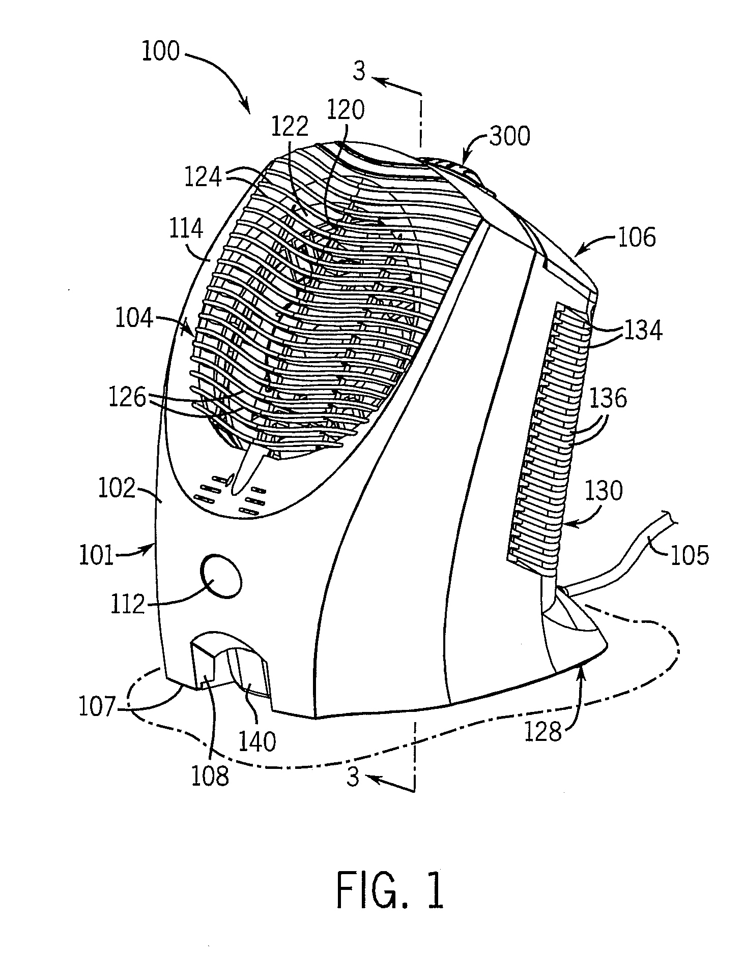
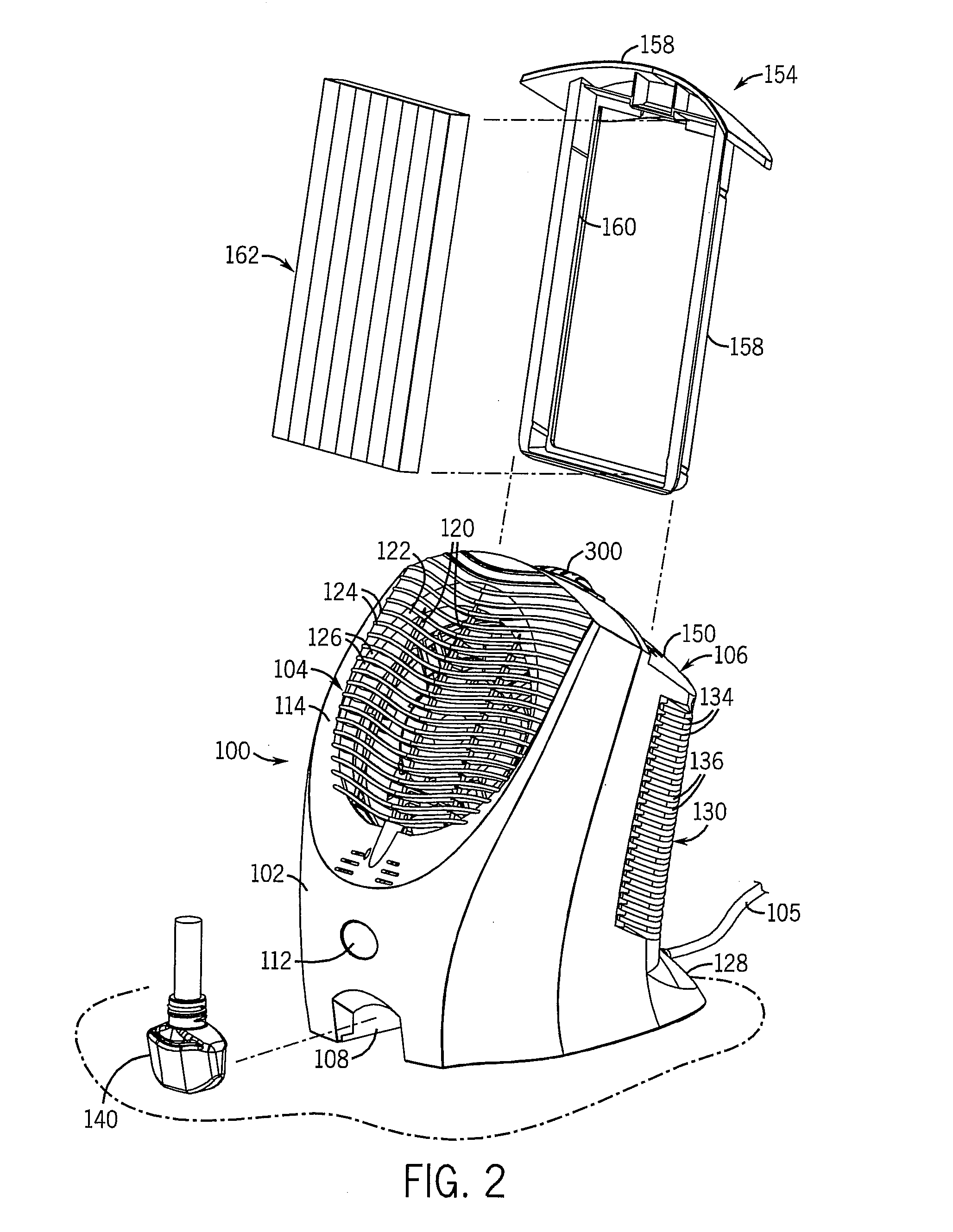
[0060] Referring now to FIGS. 9-18, the air purifier device constructed according to the present invention is indicated generally at 1000. The device 1000 includes a front housing 1002 and a rear housing 1004 each secured to one another and cooperating to form a top 1006 and a bottom 1008 for the device 1000.

[0061] As best shown in FIGS. 9-13, the front housing 1002 of the device 1000 is formed of a unitary piece 1010 of a non-conductive, and preferably plastic material having a lower, inlet port 1012 and an upper, outlet port 1014. The lower port 1012 is formed with a generally arch-like shape, and the upper port 1014 is preferably formed to be generally circular in shape, though any other suitable shapes can also be utilized for the port 1012 and 1014. The front housing 1002 is also formed to position the ports 1012 and 1014 at an angle with respect to one another, for reasons to be described.

[0062] The front housing 1002 is joined to the rear housing 1004 generally opposite the ...

third embodiment

[0089] In the present invention, best shown in FIG. 19, the device 1000 shown in FIGS. 9-18 is modified to omit the plug deck assembly 1026, and substitute therefore an power module 1200 including an electric cord 1202. The power module 1200 is operably connected to the ionizing assembly 1044, the control unit 1074 and the fan assembly 1086, similarly to the pug deck assembly 1026, in order to supply power to the device 1000 via a receptacle in which a plug (not shown) on the cord 1202 is inserted. The cord 1202 extends rearwardly from a housing 1204 for the module 1200 secured to the rear housing 1004 of the device 1000 opposite the chamber 1030. The housing 1204 has a foot 1206 disposed on a lower surface thereof that, in conjunction with a pair of supports 1208 attached to and extending downwardly from the bottom 1008 of the device 1000, allows the device 1000 to be positioned upon a flat surface 1210, such as a table, shelf, desk, or the like, to provide air purification to the ...


PUM

PropertyMeasurementUnit
angleaaaaaaaaaa
angleaaaaaaaaaa
angleaaaaaaaaaa

Abstract

The present invention is an air purifier including an ionizing assembly that operates to charge particulate material in an air flow passing through the purifier. The charged particulate material is attracted to and retained by a filter element disposed downstream of the ionization assembly and having an electrical charge opposite to the charged particulate material. The purified air passing through the filter is directed out of the device, optionally in conjunction with a fragrance that is added to the purified air flow. The ionizing assembly is formed with a ground member disposed adjacent the ionizing member to keep the electrons generated by the ionizing assembly within the purifier, and thus prevent static discharges from occurring outside of the purifier. The air flow is directed by a fan through the purifier in an angular and substantially laminar manner, such that the efficiency of the purifier is increased.

Description

CROSS-REFERENCE TO RELATED APPLICATIONS [0001] This application claims priority from Provisional U.S. Patent Application Ser. No. 60 / 707,350, filed on Aug. 11, 2005, and Provisional U.S. Patent Application Ser. No. 60 / 707,076, filed on Aug. 10, 2005, each of which are incorporated herein by reference in their entirety.BACKGROUND OF THE INVENTION [0002] 1. Field of the Invention [0003] The present invention relates to air-cleaning devices. In particular, this invention relates to air-cleaning devices that provide air purification using an ionizer and an ion precipitator that are positionable on a surface or supportable by a conventional wall electrical outlet. [0004] 2. Discussion of the Related Art [0005] The increase of outdoor air pollution over many years has created a greater awareness for the type of damage that outdoor air pollution can cause to one's health. What is not commonly known, however, is that indoor air pollution also exists and can have a significant effect on one'...

Claims


Application Information

Patent Timeline
Patent Type & Authority Applications(United States)
IPC IPC(8): B03C3/011
CPCB01D45/06B01D45/08B01D53/32B03C3/017F24F2003/1682B03C3/32B03C3/368F24F3/166B03C3/155F24F8/192F24F8/30Y10S261/88Y02A50/20
Inventor ADAIR, JOEL E.BELAND, RENE MAURICECRAPSER, JAMES R.EAGLETON, C. SCOTTGASPER, THOMAS P.GRUBER, DENNIS W.HARWIG, JEFFREY L.VARANASI, PADMA PRABODH
Owner SC JOHNSON & SON INC
Why Eureka
Try Eureka