Photovoltaic module comprising a plurality of bifacial cells and method for producing such a module

a photovoltaic module and bifacial cell technology, applied in the direction of basic electric elements, electrical apparatus, semiconductor devices, etc., can solve the problems of electrical (interconnection breakage) or mechanical (fissuring) failure of said modul

Active Publication Date: 2017-08-17
COMMISSARIAT A LENERGIE ATOMIQUE ET AUX ENERGIES ALTERNATIVES
View PDF2 Cites 2 Cited by
  • Summary
  • Abstract
  • Description
  • Claims
  • Application Information

AI Technical Summary

Benefits of technology

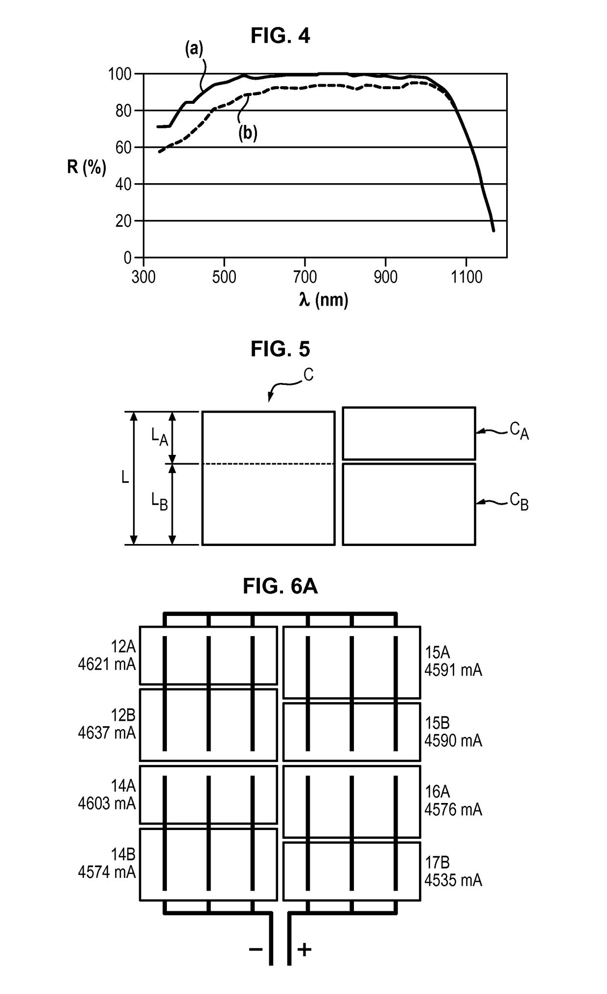
[0058]FIG. 7 is a graph presenting the gain in maximum power (Pmax) and in short-circuit current (Isc) as a function of the illumination for a photovoltaic module according to the invention,
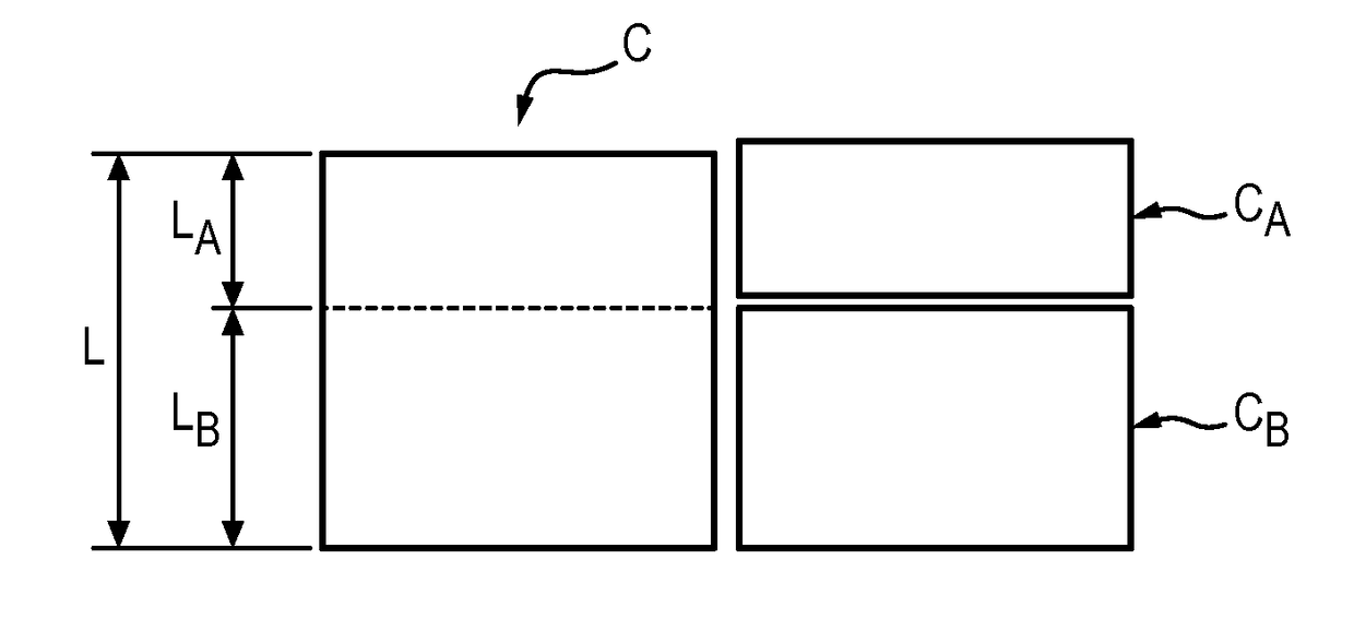
[0059]FIGS. 8A and 8B illustrate variants of cutting a bifacial cell taking

Problems solved by technology

The crossing of the strip from the front face to the rear face requires a deformation of the strip, which is capable of creating mechanical stresses in said strip, favourin

Method used


Image

  • Photovoltaic module comprising a plurality of bifacial cells and method for producing such a module
  • Photovoltaic module comprising a plurality of bifacial cells and method for producing such a module
  • Photovoltaic module comprising a plurality of bifacial cells and method for producing such a module

Examples


Embodiment Construction

[0062]The method for producing a photovoltaic module includes the successive steps described hereafter.

[0063]The photovoltaic module is intended to be produced by monolithic assembly of a plurality of bifacial cells. Said photovoltaic module has a front face and a rear face.

[0064]Firstly, from a batch of bifacial cells intended to form the module, the short-circuit current (noted Isc, expressed in mA) is determined for each of the faces of the cell. By convention, the front face (FAV) of the cell is the face of the cell for which the short-circuit current Isc is the largest and the rear face (FAR) of the cell is that for which the short-circuit current is the smallest of the two measured. The short-circuit current ratio B between the rear face and the front face is deduced from these measurements.

[0065]As an example, table 1 below illustrates the properties of the front face and of the rear face of a batch of nine cells.

[0066]The physical quantity Voc designates the voltage of the o...


PUM


Abstract

The invention concerns a method for producing a photovoltaic module, comprising:•—providing a plurality of bifacial photovoltaic cells each having a short-circuit current ratio (B),•—asymmetrically cutting each cell into two portions, such that the ratio between the surface areas of said portions is substantially equal to the short-circuit current ratio (B) of said cell or to the average short-circuit ratio of the set of cells,•—juxtapositioning said cell portions in a main plane of the module in order to form pairs of cell portions chosen such that the front face of the first portion has a short-circuit current substantially equal to the short-circuit current of the rear face of the second portion, said portions being arranged such that the front face of the first portion and the rear face of the second portion coincide with the front face of the module,•—creating an electrical connection of the front face of the first portion with the rear face of the second portion.

Description

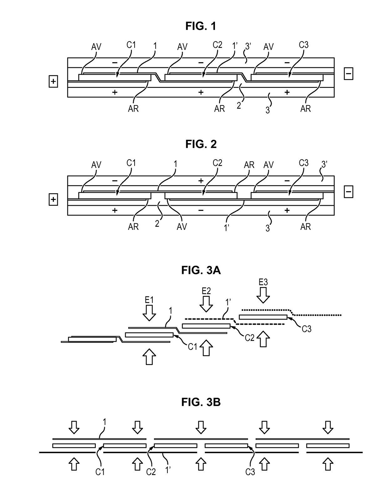
FIELD OF THE INVENTION[0001]The present invention relates to a photovoltaic module comprising a plurality of bifacial photovoltaic cells and a method for producing such a module.BACKGROUND OF THE INVENTION[0002]In a photovoltaic module, the photovoltaic cells may be connected in series by means of an electrically conducting element, such as a copper strip, which connects the front face of a cell to the rear face of the adjacent cell.[0003]In such a module, the front face of the different cells is situated on the same side, forming the front face of the module, and the rear face is situated on the opposite side, forming the rear face of the module.[0004]FIG. 1 illustrates this interconnection mode, referred to as “standard mode”, in a partial sectional view of a module comprising cells C1, C2, C3.[0005]The front face of the cells is designated by reference sign AV, the rear face is designated by reference sign AR.[0006]To connect the front face of the cell C1 to the rear face of the ...

Claims


Application Information

Patent Timeline
IPC IPC(8): H01L31/05H01L31/068H01L31/18
CPCH01L31/0508H01L31/0684H01L31/1876H01L31/042H01L31/0504Y02E10/547Y02E10/50
Inventor LEFILLASTRE, PAULGERRITSEN, ERIC
Owner COMMISSARIAT A LENERGIE ATOMIQUE ET AUX ENERGIES ALTERNATIVES
Why Eureka
Try Eureka