Quick-disconnect coupling system with emergency release feature

a coupling system and emergency release technology, applied in the direction of coupling device connection, electrically conductive connection, electric discharge lamp, etc., can solve the problems of primary latching system being subjected to force and excessive abusive disconnecting, affecting the disconnection speed, etc., to achieve the effect of facilitating disconnection (emergency releas

Active Publication Date: 2007-08-07
INTERLEMO HLDG SA
View PDF8 Cites 15 Cited by
  • Summary
  • Abstract
  • Description
  • Claims
  • Application Information

AI Technical Summary

Benefits of technology

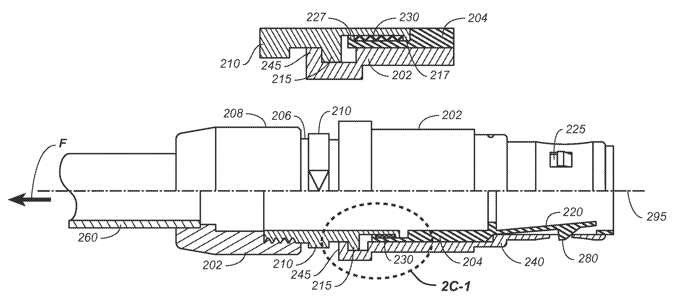
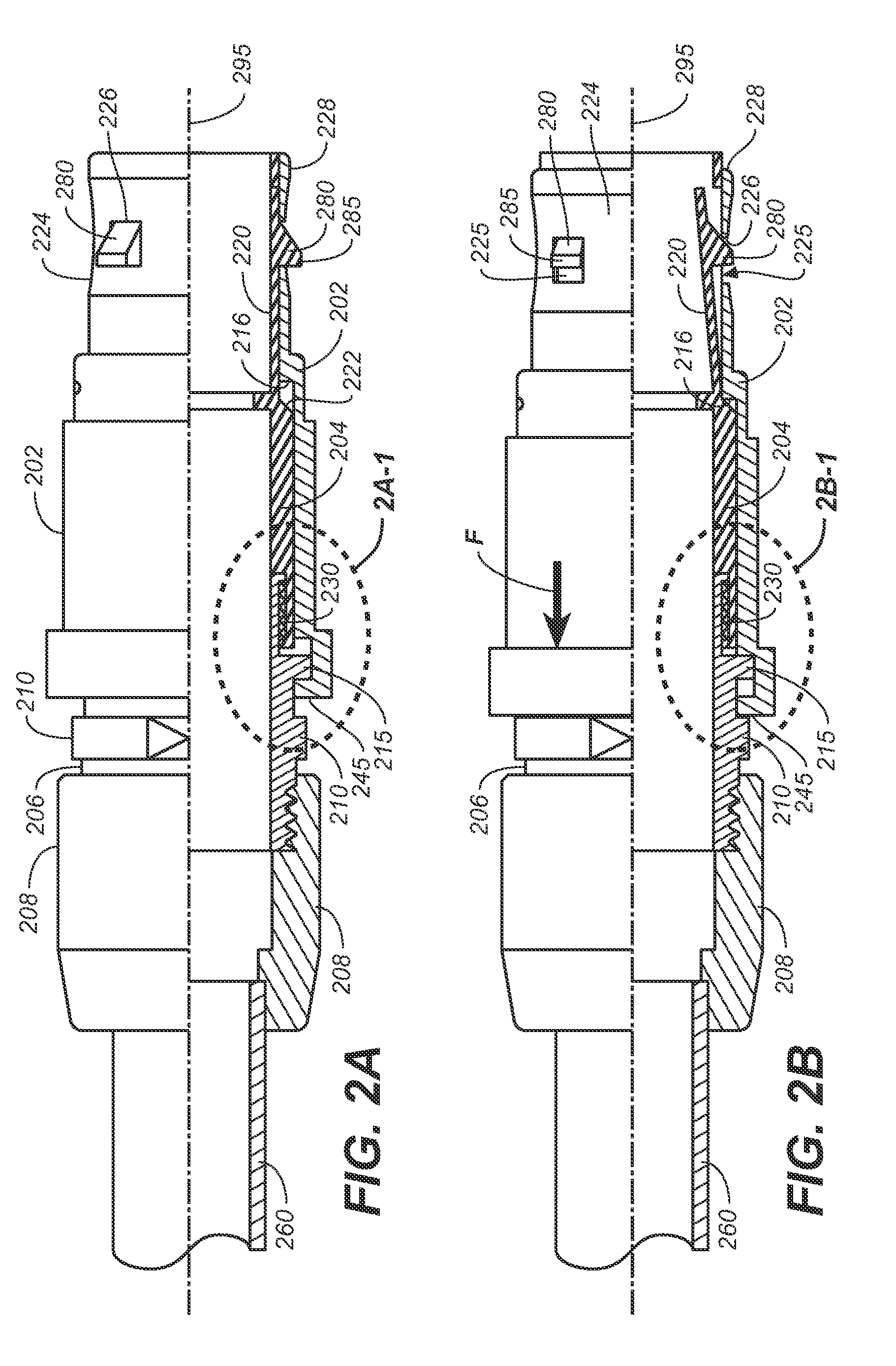
[0025]Yet another object of the present invention is to provide a quick-disconnect coupling system wherein a secondary release feature prevents damage to the components while providing standard coupling and decoupling functionality.

Problems solved by technology

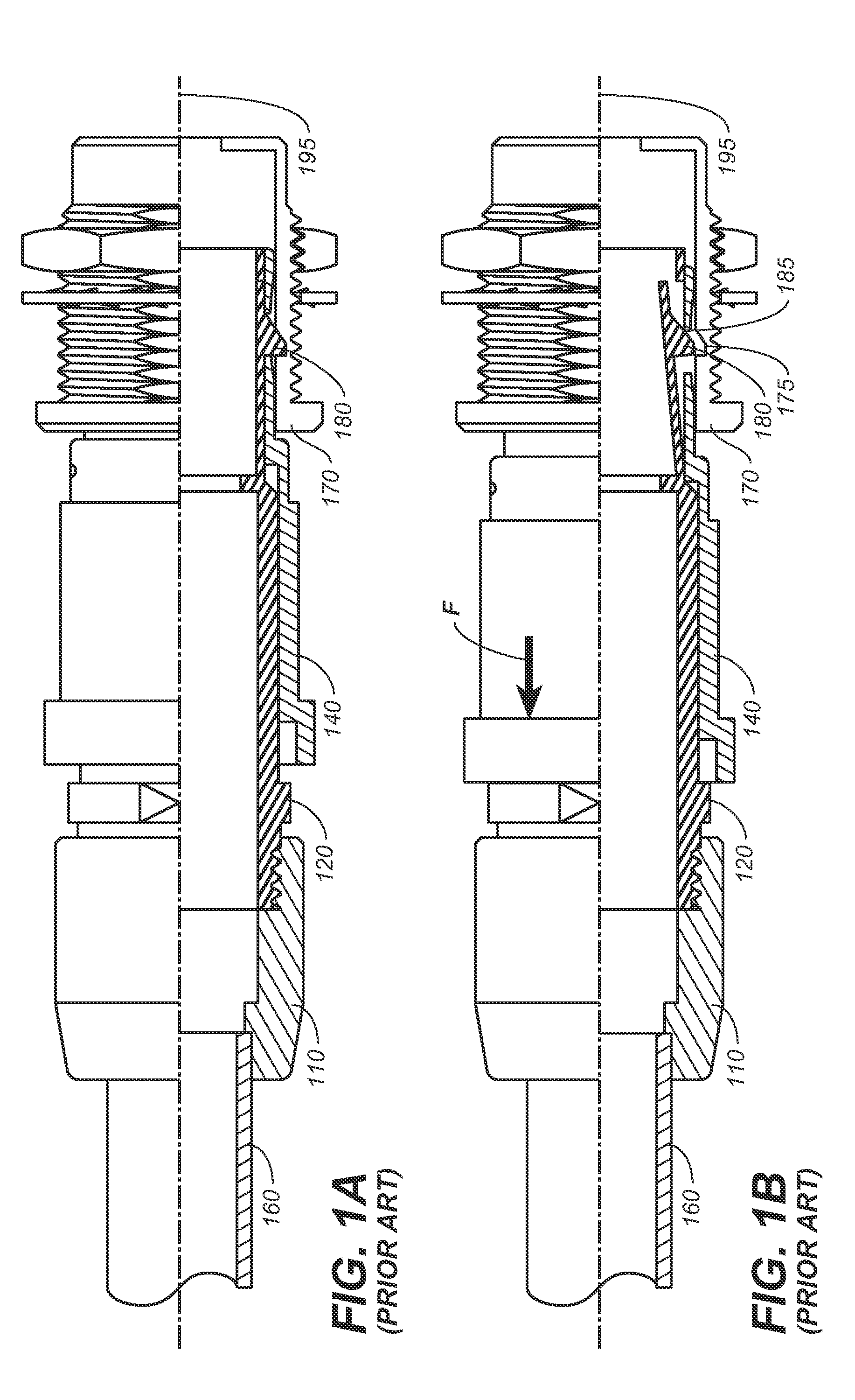
Quick-disconnect coupling devices are often used in applications requiring frequent coupling and decoupling, yet requiring a secure engagement due to the application environment having a probability of inadvertent forces being applied to the device being coupled.
Inadvertent disconnection is a concern in many applications where interruption of function would create hazardous conditions or have otherwise undesirable results or effects.
The ring-shaped coss-section permits tightening of the screw but results in the screw breaking when a predetermined force is applied to allow separation of the fittings.
This primary latching system is then subjected to forces and excessive abusive disconnects (such as cable pulls) that it was not intended to accommodate.
This typically means variation and degradation of the retention force over time.
One disadvantage of this is that the “normal” (intentional) disconnect force is higher than desired.
Also, the higher forces employed can accelerate wear and variation over time.

Method used


Image

  • Quick-disconnect coupling system with emergency release feature
  • Quick-disconnect coupling system with emergency release feature
  • Quick-disconnect coupling system with emergency release feature

Examples


embodiment 300

[0112]FIGS. 3 through 3B-1 show a second preferred embodiment 300 of the present invention, with FIGS. 3 through 3A-1 showing the coupling system as mated and prior to an emergency release feature activation, and FIGS. 3B and 3B-1 showing the system during an emergency release event.

[0113]Referring now to FIGS. 3 through 3A-1, in the second preferred embodiment, the connector comprises a proximal shell 302, a latch arm sleeve 304, and an internal clamping member 308 having a cable clamping element 310 at the distal portion. The locking latch arms 320 are mechanically loaded with force by a resilient member, where the force required to move the latch arms 320 corresponds to the desired breakaway force. The internal clamping member is functionally analogous to the medial coupler of the first preferred embodiment and contains the internal components and the clamping or mounting system 310. The clamping member is slidably inserted into the proximal shell and have movement restricted by ...

embodiment 400

[0119]FIGS. 4A through 4B-1 show a third preferred embodiment 400 of the inventive quick-disconnect coupling system with emergency release feature of the present invention. In this embodiment, the structural elements are essentially identical to those of the second preferred embodiment, shown in FIGS. 3 through 3B-1. The apparatus includes proximal shell 402 slidably insertable into a connector receptacle 470. A latching arm sleeve 404 is slidably disposed within the proximal sleeve 402 and interposed between the internal clamping member 408, the proximal extension 409 of the internal clamping member, and the proximal sleeve. The internal clamping member 408 preferably includes a clamping mechanism 410 at its distal end. The latching arm sleeve 404 extends at its proximal end into a plurality of flexible latching arms 420 having a ramp portion 480 and ramp face 485, and which may be urged inwardly or interiorly by the neck portion 424 of a release sleeve 440 integral with the proxim...


PUM


Abstract

A quick-disconnect coupling device for use in plug and receptacle style electrical connectors, fiberoptic connectors, pneumatic and hydraulic couplings or any other application where a secure quick-disconnect connection is desired. Under normal operation, the coupling device incorporates a sliding outer sleeve to activate and release latching features within the retention system, which engages with an appropriate mating receptacle. An emergency release feature is included to allow the coupling to disconnect at a selectable, predetermined axial pull-force on the rear of the coupler. The secondary release feature prevents damage to the components and, in many applications, increases personal safety, by providing an emergency release feature, while still maintaining standard coupling and decoupling functionality.

Description

CROSS REFERENCES TO RELATED APPLICATIONS[0001]The present application claims the benefit of U.S. Provisional Patent Application Ser. No. 60 / 728,859, filed Oct. 20, 2005, (Oct. 20, 2005), and U.S. Provisional Patent Application Ser. No. 60 / 740,739, filed Nov. 29, 2005 (Nov. 29, 2005).STATEMENT REGARDING FEDERALLY SPONSORED RESEARCH OR DEVELOPMENT[0002]Not applicable.THE NAMES OR PARTIES TO A JOINT RESEARCH AGREEMENT[0003]Not applicable.INCORPORATION-BY-REFERENCE OF MATERIAL SUBMITTED ON A COMPACT DISC[0004]Not applicable.BACKGROUND OF THE INVENTION[0005]1. Field of the Invention[0006]The present invention relates generally to coupling devices, and more particularly to a quick-disconnect coupling device for use in applications such as plug and receptacle style electrical connectors, fiberoptic connectors, pneumatic and hydraulic couplings or any other application where a secure quick-disconnect connection is desired.[0007]2. Discussion of Related Art Including Information Disclosed Un...

Claims


Application Information

Patent Timeline
Patent Type & Authority Patents(United States)
IPC IPC(8): H01R4/38H01R13/648
CPCH01R13/6273H01R13/6277H01R13/635
Inventor LEE, WILLIAM H.
Owner INTERLEMO HLDG SA
Why Eureka
Try Eureka