Control apparatus for opening and closing unit for vehicle
a technology for controlling apparatus and opening and closing unit, which is applied in the direction of motor/generator/converter stopper, dynamo-electric converter control, stopping arrangement, etc., can solve the problems of reducing the size and weight of the cable driving device, and generating a large load, so as to enhance the rigidity of the casing
- Summary
- Abstract
- Description
- Claims
- Application Information
AI Technical Summary
Benefits of technology
Problems solved by technology
Method used
Image
Examples
first embodiment
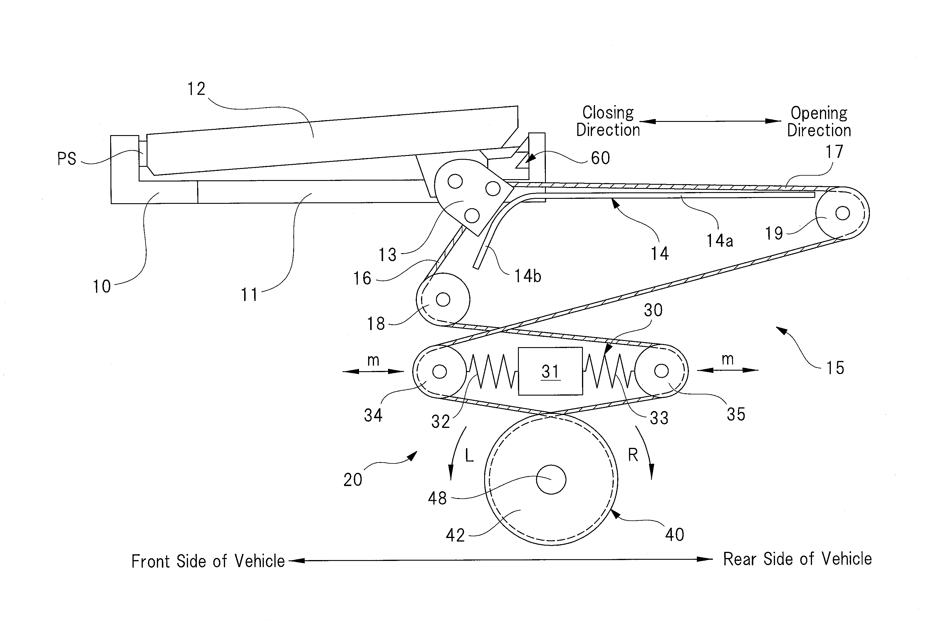
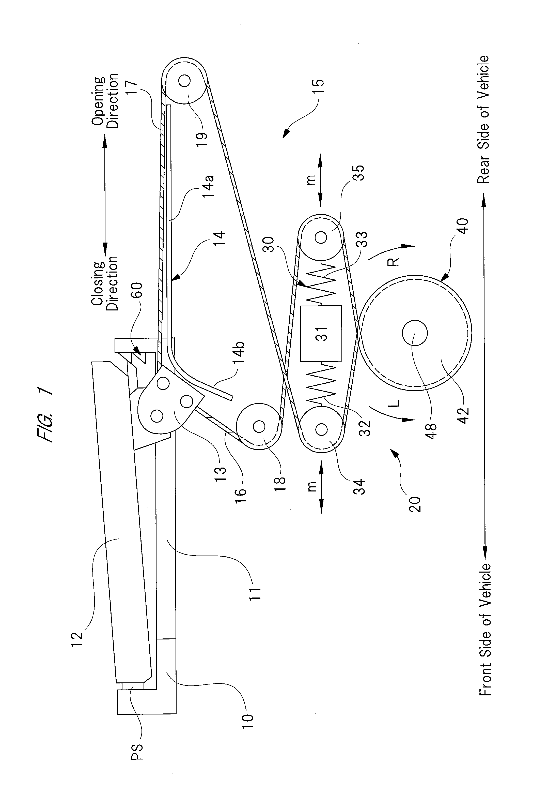
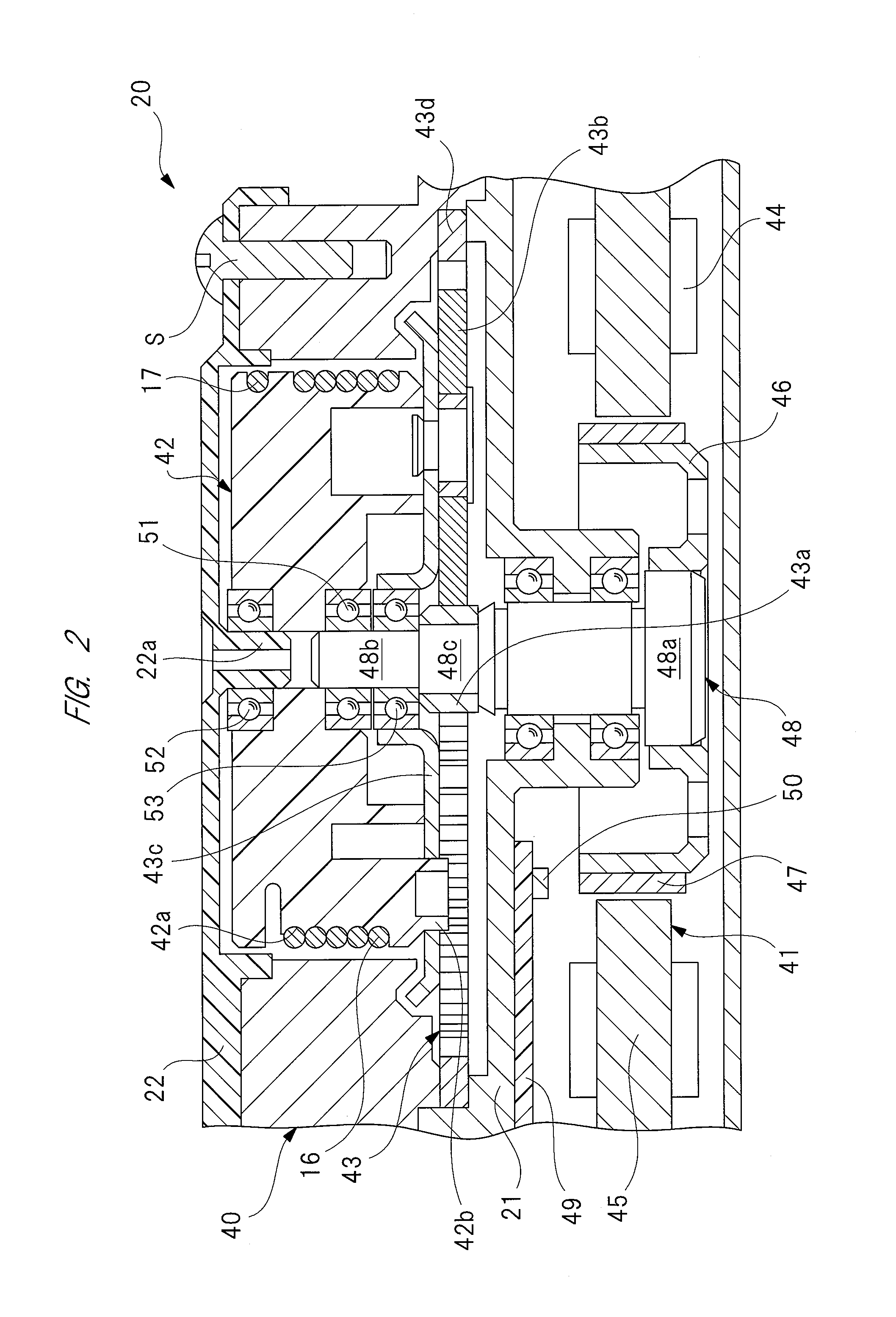
[0092]As described above in detail, the controller 80 allows the sliding door 12 to be opened and closed by driven by the electric motor 41 when the main switch 82 is in the on-state, and performs a braking control to generate a braking force at the electric motor 41 when the main switch 82 is in the off-state and the half-latch switch 66 is in the on-state. Therefore, when the main switch 82 is in the on-state, the sliding door 12 can be opened and closed automatically. On the other hand, when the main switch 82 is in the off-state and the sliding door 12 is closed manually, the half-latch switch 66 is switched on before the sliding door 12 is put in the full-latch state, so that the controller 80 performs a braking control of the electric motor 41. In this manner, even if the casing is not enhanced in rigidity, damage to the components caused by the inertial force of the electric motor 41 generated by the sliding door stopped can certainly be prevented.
[0093]Next, the second embo...
second embodiment
[0094]FIGS. 9A to 9C are explanatory diagrams each explaining a state of braking control according to a
[0095]The second embodiment is different from the first embodiment only in braking control of the electric motor 41 performed by the controller 80, but other elements and the like of the second embodiment are the same as those of the first embodiment. Specifically, in the first embodiment, a closed circuit is formed in the driving circuit 90 (see FIG. 5) of the electric motor 41, thereby causing the electric motor 41 to generate a braking force.
[0096]On the other hand, according to the second embodiment, when the half-latch switch 66 (see FIG. 3) is turned on, that is, when a judgment “yes” is made in step S13 of FIG. 6, the control signal output unit 86 of the controller 80 supplies a braking drive current BI to each of the U-phase coil 44u, V-phase coil 44v, and W-phase coil 44w which correspond to the respective rotation positions of the rotor 46, as shown in FIGS. 9A, 9B, and 9...
PUM
 Abstract
Description
Claims
Application Information
 - R&D
- Intellectual Property
- Life Sciences
- Materials
- Tech Scout
- Unparalleled Data Quality
- Higher Quality Content
- 60% Fewer Hallucinations
Browse by: Latest US Patents, China's latest patents, Technical Efficacy Thesaurus, Application Domain, Technology Topic, Popular Technical Reports.
© 2025 PatSnap. All rights reserved.Legal|Privacy policy|Modern Slavery Act Transparency Statement|Sitemap|About US| Contact US: help@patsnap.com


