
Control device for engine driven vehicle incorporating generator

a technology of control device and engine, which is applied in the direction of electric generator control, electric control, instruments, etc., can solve the problems of vehicle runaway, engine rotational speed may exceed the target rotational speed, and damage to electronic components of the circuit closer to load, so as to achieve excessively increase the rotational speed of the engine

Inactive Publication Date: 2006-12-12
KOKUSAN DENKI CO LTD
View PDF2 Cites 2 Cited by
  • Summary
  • Abstract
  • Description
  • Claims
  • Application Information

AI Technical Summary

Benefits of technology

The control device effectively prevents damage to generator-connected circuits by limiting engine rotational speed and stopping the engine when errors occur, ensuring safe operation and protecting components from excessive speed-related damage.

Problems solved by technology

In the vehicle having the generator for driving the external load as described above, if a gear position of a power transmission device provided between a crankshaft of the engine and driving wheels is in a position for transmitting power (a position other than a neutral position or a parking position) in error when the generator is driven, an increase in the rotational speed of the engine for driving the generator may cause runaway of the vehicle.
However, in the control mode for generating electric power, the output voltage of the generator is necessarily in a state of application to the circuit closer to the load, and therefore an excessive increase in the rotational speed of the engine may cause damage to electronic components of the circuit closer to the load.
However, when a driver operates an axle in error to open the throttle valve during generation, or when an abnormality occurs in the engine output control device, the rotational speed of the engine may increase to exceed the target rotational speed.
In this case, the ECU accepts the increase in the rotational speed of the engine up to the limit rotational speed set to an upper limit value of the rotational speed of the engine accepted while vehicle driving, which may cause damage to the components of the circuit closer to the load than the generator.

Method used


Image

  • Control device for engine driven vehicle incorporating generator
  • Control device for engine driven vehicle incorporating generator
  • Control device for engine driven vehicle incorporating generator

Examples


Embodiment Construction

[0037]Now, embodiments of the invention will be described with reference to the drawings.

[0038]An engine driven vehicle to which the invention is applied may be an ATV (a buggy), a tractor, a recreational vehicle, or the like, that incorporates a power supply unit that uses a generator mounted to an engine for driving the vehicle as a power supply to generate an AC power at a commercial frequency, and use, a structure, and a type of the vehicle are arbitrary.

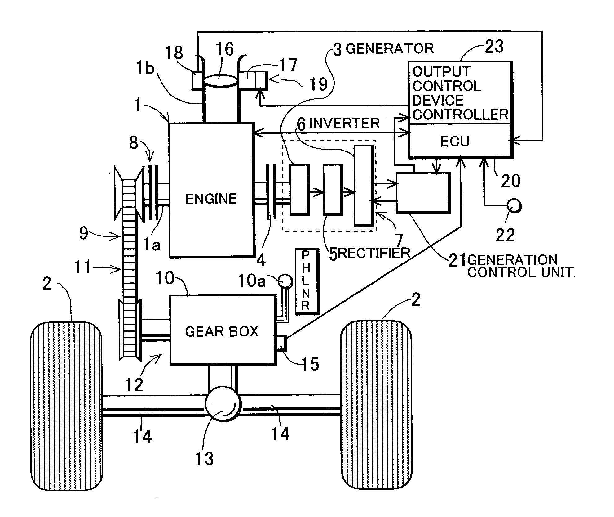
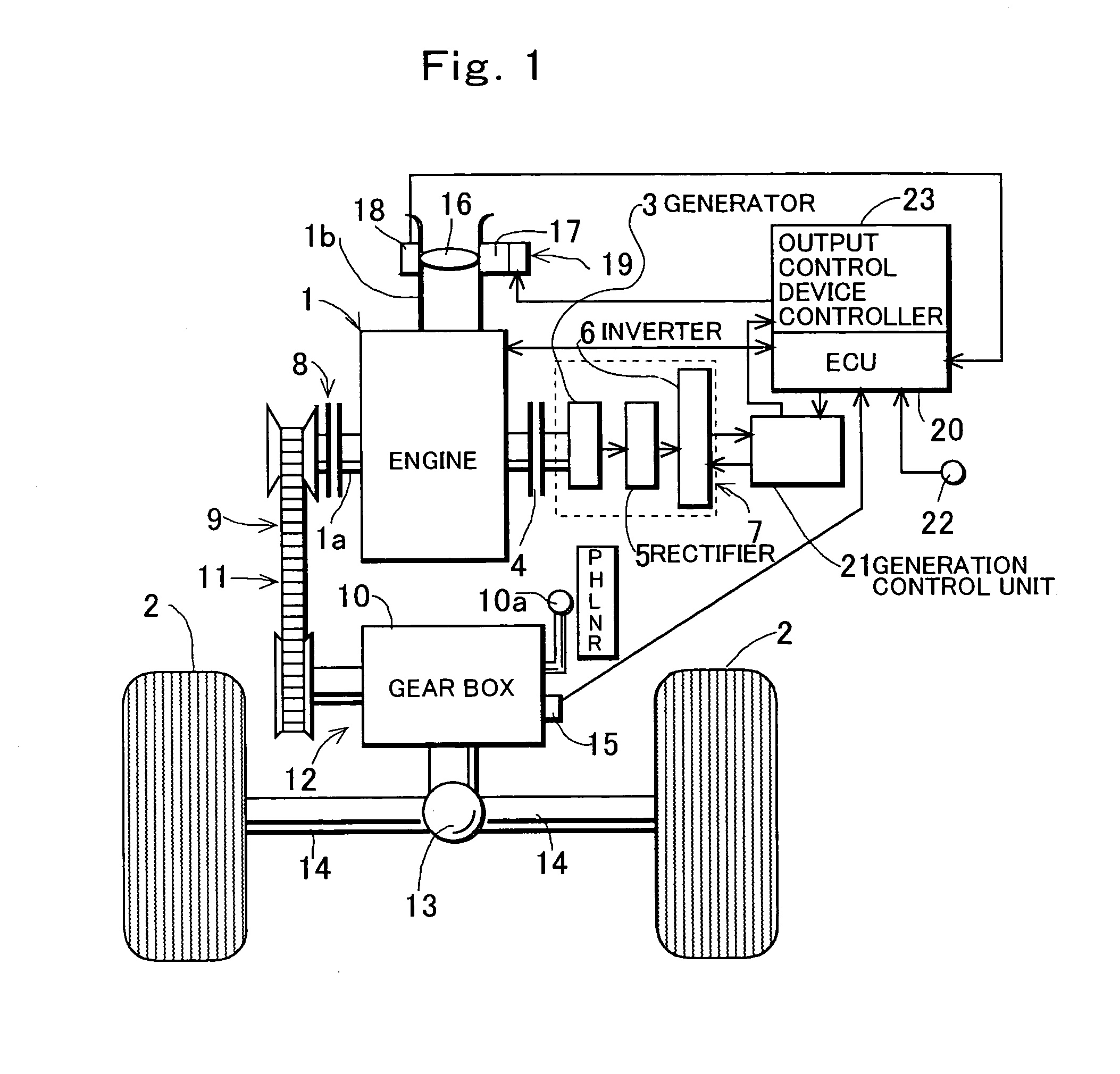
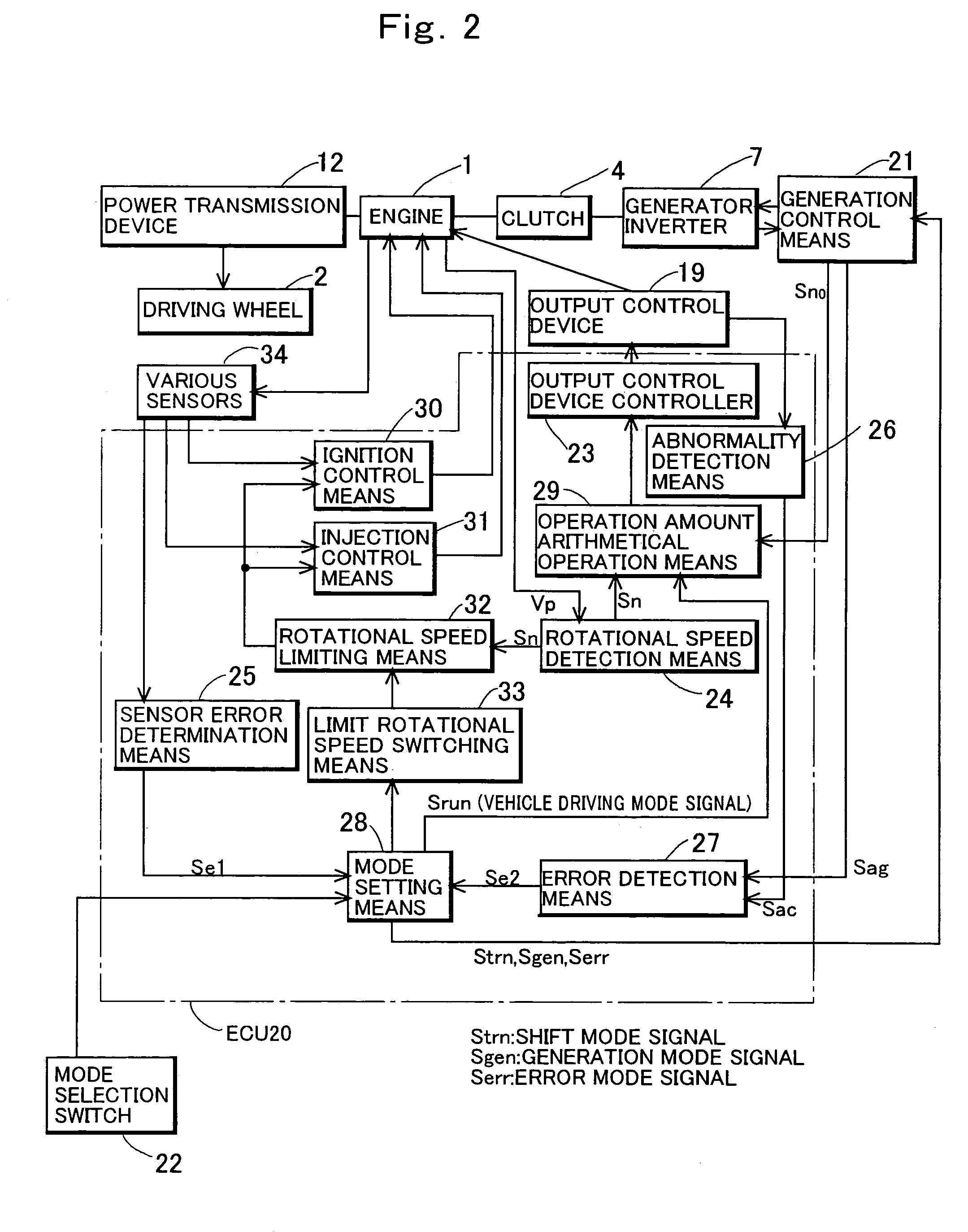
[0039]FIG. 1 shows an example of a whole construction of the engine driven vehicle to which the invention is applied, and FIG. 2 is a block diagram of a whole construction of the embodiment of the invention. In FIG. 1, a reference numeral 1 denotes an engine incorporated in a vehicle body (not shown) having driving wheels 2, a reference numeral 3 denotes a magneto AC generator that is incorporated in the vehicle body together with the engine 1 and whose rotor has a rotation axis connected to an end of a crankshaft 1a of the engi...


PUM


Abstract

A control device for controlling an engine driven vehicle that drives a generator by an engine to supply power to an external load when the vehicle is stopped, including: rotational speed limiting means for controlling to limit a rotational speed of the engine to a limit rotational speed or lower corresponding to an upper limit value accepted while driving when the vehicle is driven, and to limit the rotational speed of the engine to a limit rotational speed or lower corresponding to a rotational speed slightly higher than an upper limit value of the rotational speed required for supplying power from the generator to the external load when the vehicle is stopped to supply power from the generator to the external load.

Description

TECHNICAL FIELD OF THE INVENTION[0001]The present invention relates to a control device for an engine driven vehicle that drives a generator by an engine when the vehicle is stopped and supplies power from the generator to an external load.BACKGROUND OF THE INVENTION[0002]Engine driven vehicles are known, which drive a generator by an engine when driving is stopped to supply power to an external load. Such a vehicle is disclosed, for example, in Japanese Patent Laid-Open No. 2001-231106.[0003]In recent years, in engine driven vehicles such as ATVs (All Terrain Vehicles, so-called buggies), tractors, or recreation vehicles that are designed for driving on rough ground, a commercial AC output of AC 100 V or AC 200 V (50 Hz or 60 Hz) has been supplied from a power supply unit that uses a generator driven by an engine as a power supply to an external load in a separate system from electrical components of the vehicle such as an ignition device, a fuel injection device, a head light, or ...

Claims


Application Information

Patent Timeline
Patent Type & Authority Patents(United States)
IPC IPC(8): F02D31/00F02D29/02F02D45/00F02D29/06F02D41/02F02D41/14F02D41/22H02P9/04
CPCF02D29/06F02D31/006F02D41/021H02P9/04
Inventor KISHIBATA, KAZUYOSHIKITAGAWA, YUICHISATO, HIROYASU
Owner KOKUSAN DENKI CO LTD
Learn More