Electrical connector for a flat-type cable

a flat-type cable and electric connector technology, applied in the direction of coupling contact members, coupling device connections, coupling parts, etc., to achieve the effect of long shap

Inactive Publication Date: 2007-08-14
HIROSE ELECTRIC GROUP
View PDF25 Cites 32 Cited by
  • Summary
  • Abstract
  • Description
  • Claims
  • Application Information

AI Technical Summary

Benefits of technology

[0012]In view of the above problems, an object of the invention is to provide a connector, in which each latching claw is surely latched onto the latching portion, such as the latching holes of a cable, and does not apply excess stress to the latching metallic pieces when the pressuring member is at the closed position.
[0013]The electrical connector for a flat-type cable according to the invention is comprised of an insulating housing, a plurality of terminals, which is arranged and held by the housing and is connected to a flat-type cable, latching metallic pieces, which are arranged in parallel with the plurality of terminals, pressuring members, which are freely rotatable between the open position for receiving the flat-type cable and the closed position for increasing the contact pressure to the terminals of the flat-type cable. Since each latching metallic piece has a latching claw that elastically displaces, it latches onto the latching sections of the cable, and therefore coming off of the flat-type cable from the connector is prevented.
[0014]In the electrical connector for a flat-type cable according to the invention, each latching metallic piece has a lever-like arm that extends in the direction of receiving the flat-type cable, and has a latching claw at one end of the lever-like arm, a fulcrum section at the middle point, and an extending section at the other end. The pressuring member has a restricting section that does not contact with the extending section when it is at the open position, but that prevents the displacement of the extending section when it is at the closed position. The pressuring member is in a condition that it can be freely displaced, so that the lever-like arm allows the flat-type cable inserted / removed to / from the connector when the pressuring member is at the open position. When it is at the closed position, the pressuring member does not allow the displacement of the lever-like arm in the direction that increases the latching of each latching claw onto the latching section, and prevents the displacement of the lever-like arm in the direction that reduces the latching when the pressuring member is at the closed position.
[0015]According to the connector of the above-described constitution according to this invention, the pressuring member does not contact with the lever-like arm when it is at the open position, and the lever-like arm is pressed by the front end of the flat-type cable when the cable is inserted to the connector, and freely displaces so as to allow the insertion of the flat-type cable. Once the flat-type cable is inserted to a specified position, each latching claw provided at one end of the lever-like arm latches onto the latching section of the flat-type cable, and maintains its latching condition, reducing the displacement of the lever-like arm. After that, the pressuring member is moved to the closed position and the flat-type cable is pressed to the contact section of each terminal. Once the pressuring member is moved to the closed position, the pressuring member prevents at the extending section, which is provided at the other end of the lever-like arm, the displacement of the lever-like arm in the direction that reducing the latching without applying a pressing force that increases the latching to the extending section. Accordingly, the lever-like arm does not generate any internal stress when each latching claw latches onto the latching section of the flat-type cable at a normal condition. Only when the cable is carelessly pulled in the cable-removal direction and the extending section becomes displaced receiving a force from the latching section at the latching claw, the lever-like arm receives temporary internal stress, which is a blocking force from the restricting section of the pressuring member.
[0018]Furthermore, according to the invention, each latching metallic piece is mounted to the housing by inserting to corresponding slit of the housing from the side opposite the side for receiving the flat-type cable. In addition, each latching metallic piece has a stopper protrusion, which faces the corresponding portion of the housing at a specified inserting position, at least one of arms, i.e., the upper arm or the lower arm. In this case, if the cable receives unexpected force in the cable-removal direction, the stopper section of each latching metallic piece contacts with the corresponding section of the housing, which enables the displacement of the upper arm. Therefore, the connecting section that has relatively thin and long shape can be prevented from plastic deformation in the cable-removal direction, and provides resistance against the cable via the latching metallic pieces.
[0019]As described above, according to the invention, when the pressuring member is at the closed position, the restricting section of the pressuring member does not exert a force to the extending section of each latching metallic piece in the direction that increases the latching, and the displacement of the lever-like arm in the direction that reduces the latching of the latching claw is restricted at the lever section. Therefore, the latching can be surely maintained, and excess stress would not be applied to the latching metallic piece. In addition, the latching metallic piece would not be plastically deformed even when a force in the cable-removal direction is unexpectedly applied to the cable, and the latching metallic piece can maintain its functions over a long period of time.

Problems solved by technology

When it is at the closed position, the pressuring member does not allow the displacement of the lever-like arm in the direction that increases the latching of each latching claw onto the latching section, and prevents the displacement of the lever-like arm in the direction that reduces the latching when the pressuring member is at the closed position.

Method used


Image

  • Electrical connector for a flat-type cable
  • Electrical connector for a flat-type cable
  • Electrical connector for a flat-type cable

Examples


Embodiment Construction

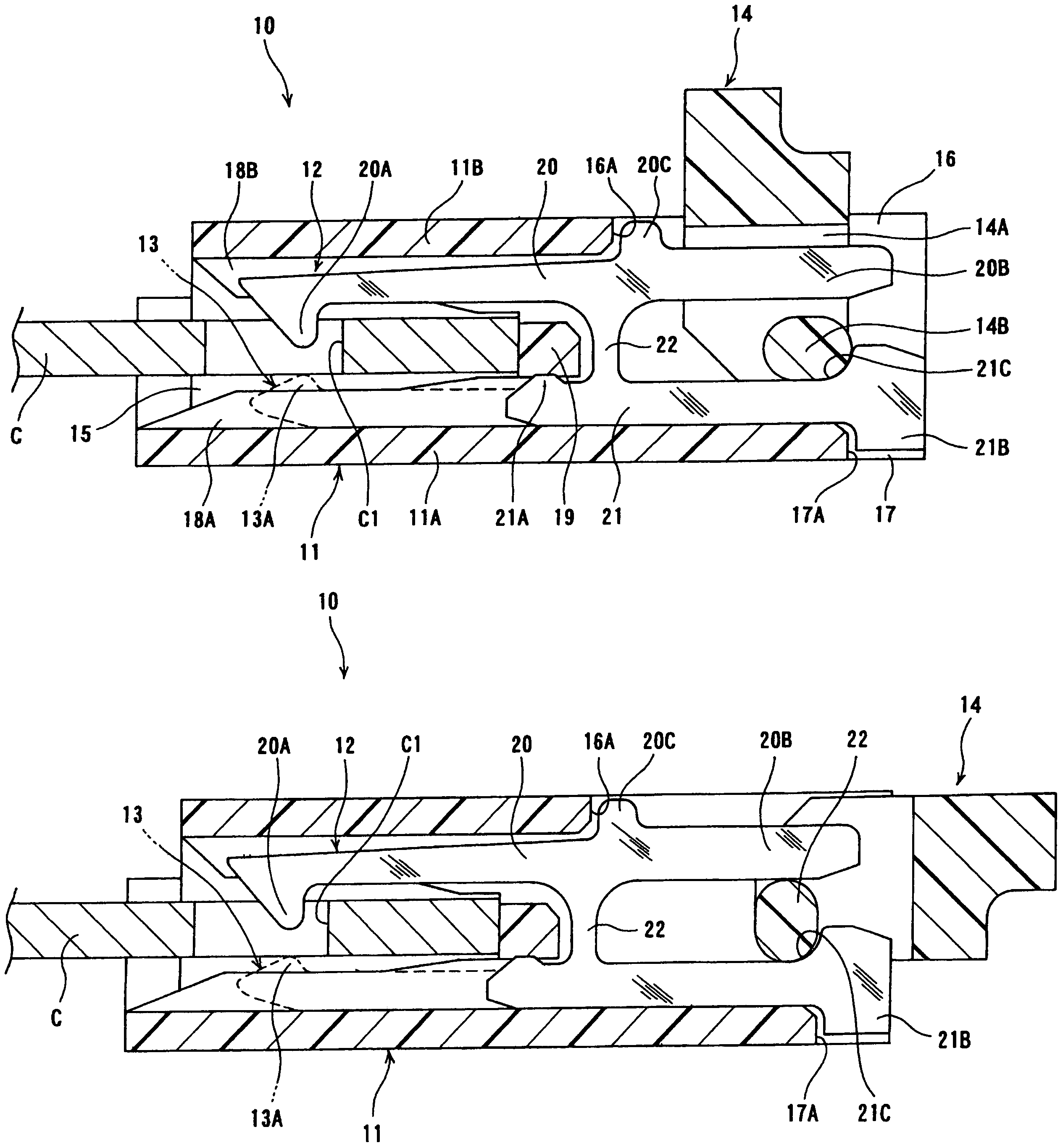
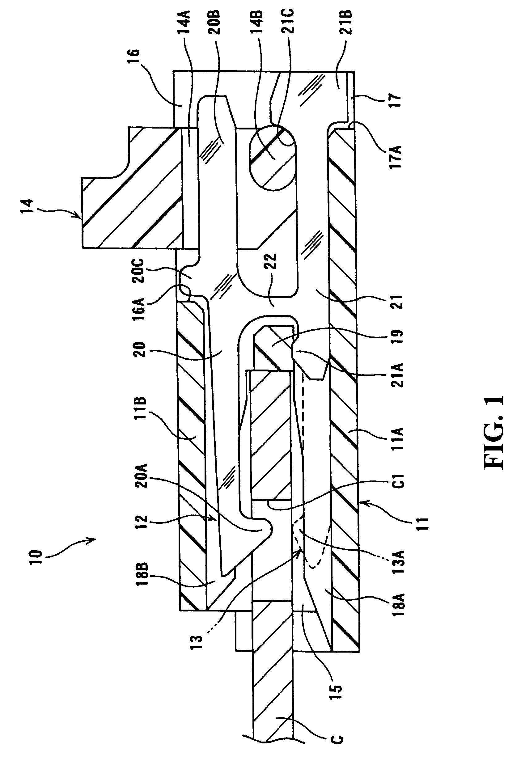
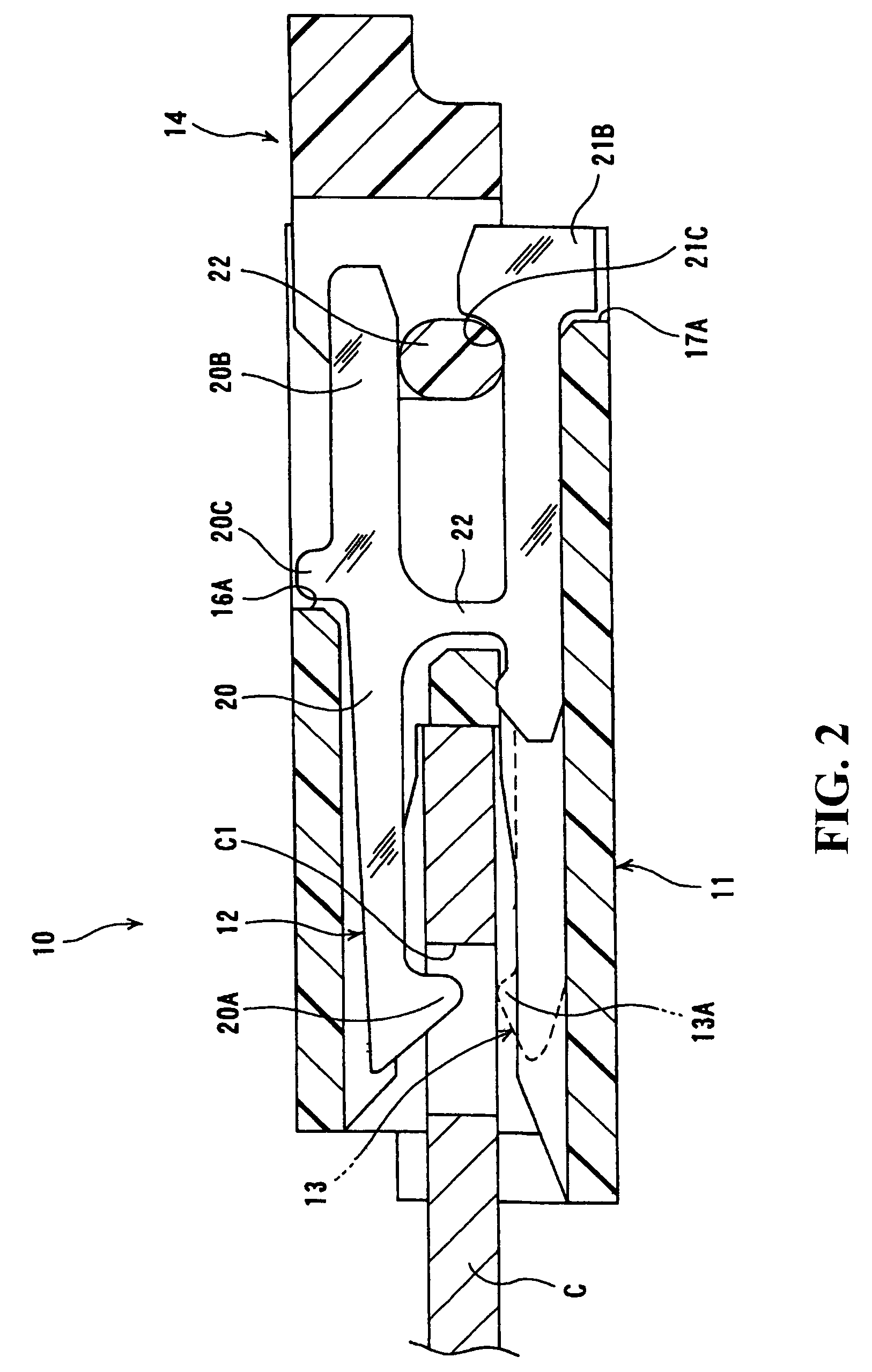
[0023]Embodiments of the invention will now be described with reference to the accompanying drawings, FIGS. 1 and 2.

[0024]The electrical connector illustrated in FIG. 1 is mounted on a circuit board, and terminals are connected by soldering to a corresponding circuit unit of the circuit board at their connecting sections. On the other hand, the connector receives a flat-type cable from its opening, and the flat cable is connected with the above-described circuit unit via the terminals. Here, a flat-type cable includes so-called flat cable and flexible circuit board, etc.

[0025]In the connector 10 of FIG. 1, latching metallic pieces 12 and terminals 13 are held in an insulating housing 11 that has an outer shape of generally rectangular parallelpiped. A pressuring member 14 is supported by the latching metallic piece 12 and the terminal 13 so as to be freely rotatable. The housing 11 has a bottom wall 11A, which is arranged contacting with a circuit board by the surface, an upper wall...


PUM


Abstract

The latching metallic piece (12) has a lever-like arm (20) that extends in the direction of receiving the flat-type cable C. The lever-like arm (20) has a latching claw (20A) at one end, a fulcrum section (22) at the middle point, and an extending section at the other end. A pressuring member (14) has a restricting section that does not contact with the extending section (20B) of the latching metallic piece (12) at the open position, and that prevents the displacement of the extending section at the closed position. When the pressuring member is at the open position, the lever-like arm (20) is in the state that it can be freely displaced so as to allow insertion / removal of the flat-type cable. When the pressuring member is at the closed position, the displacement of the lever-like arm relative to the latching section in the direction that increases the latching of the latching claw (20A) is prevented, and the displacement of the lever-like arm in the direction that reduces the latching is prevented.

Description

BACKGROUND OF THE INVENTION[0001]1. Field of the Invention[0002]The present invention relates to an electrical connector for a flat-type cable.[0003]2. Description of the Related Art[0004]For an electrical connector for a flat-type cable, such as a flat cable and a flexible circuit board, for example, a connector disclosed in Patent Reference 1 is known. In the connector of Patent Reference 1, a plurality of terminals formed by punching a metal sheet is arranged such that the sheet surfaces are parallel to each other. A latching metallic piece 20 having similar shape to that of the terminals as shown in the accompanying drawing, FIG. 3(A), is provided at the both ends of the arrangement.[0005]As shown in the figure, each latching metallic piece 50 has generally H-shape, and has an upper arm 51 and a lower arm 52, which are connected by a connecting section 53. The upper arm 51 has flexibility to displace upward / downward, while the connecting section 53 works as the fulcrum, and has ...

Claims


Application Information

Patent Timeline
Patent Type & Authority Patents(United States)
IPC IPC(8): H01R13/15H01R12/79
CPCH01R13/629H01R13/639H01R12/79H01R12/88H01R12/77H01R24/20
Inventor TAKASHITA, YOSHINORI
Owner HIROSE ELECTRIC GROUP
Why Eureka
Try Eureka