Device for detecting absolute rotation angle and torque

a technology of absolute rotation angle and torque, which is applied in the direction of electrical steering, instruments, transportation and packaging, etc., can solve the problem that the above-mentioned detector cannot detect an absolute rotation angl

Inactive Publication Date: 2007-08-21
PANASONIC CORP
View PDF17 Cites 17 Cited by
  • Summary
  • Abstract
  • Description
  • Claims
  • Application Information

AI Technical Summary

Problems solved by technology

The conventional detector discussed above cannot detect an absolute rotation angle.

Method used


Image

  • Device for detecting absolute rotation angle and torque
  • Device for detecting absolute rotation angle and torque
  • Device for detecting absolute rotation angle and torque

Examples


Embodiment Construction

[0019]An exemplary embodiment of the present invention is demonstrated hereinafter with reference to the accompanying drawings.

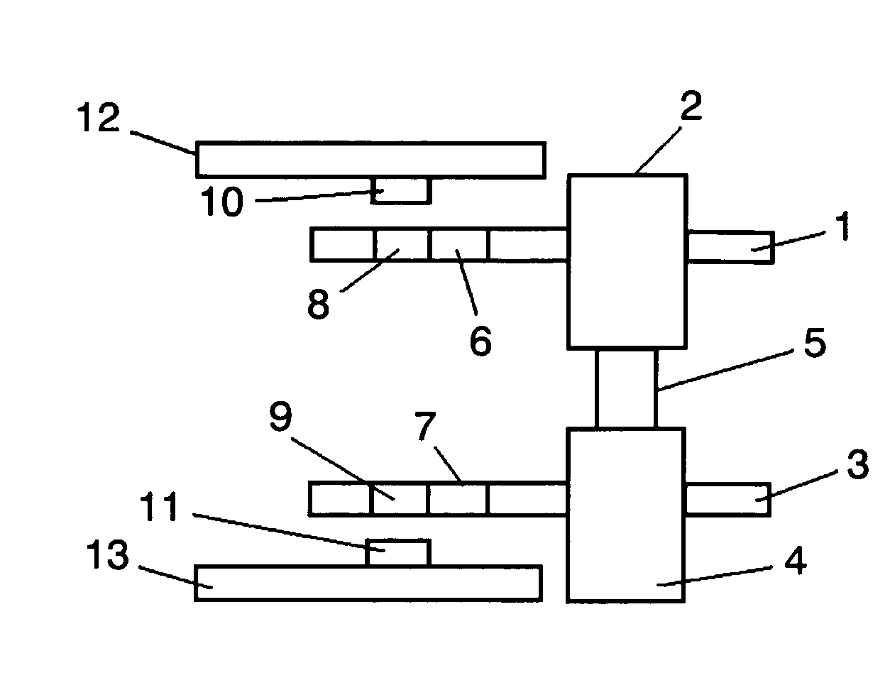
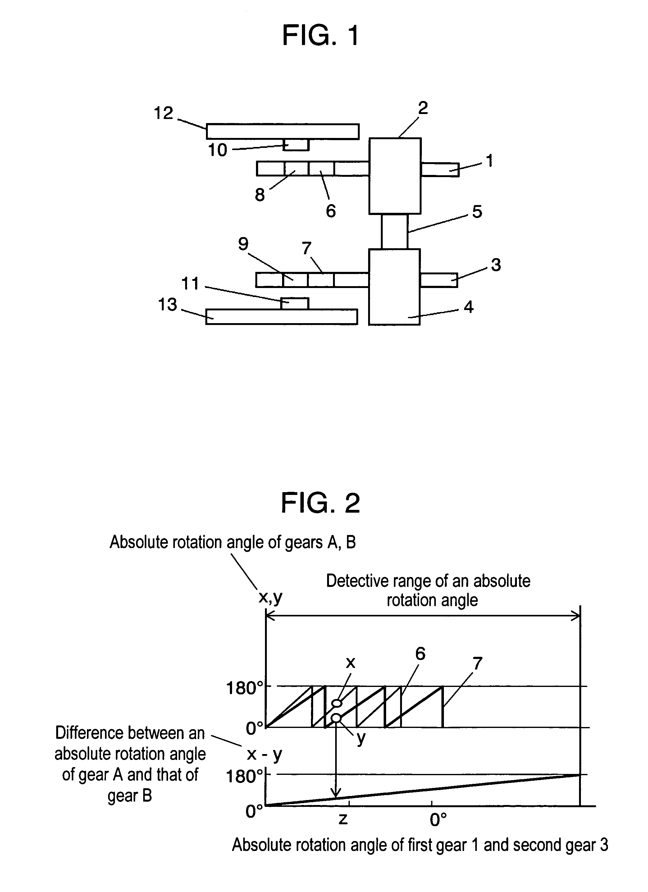
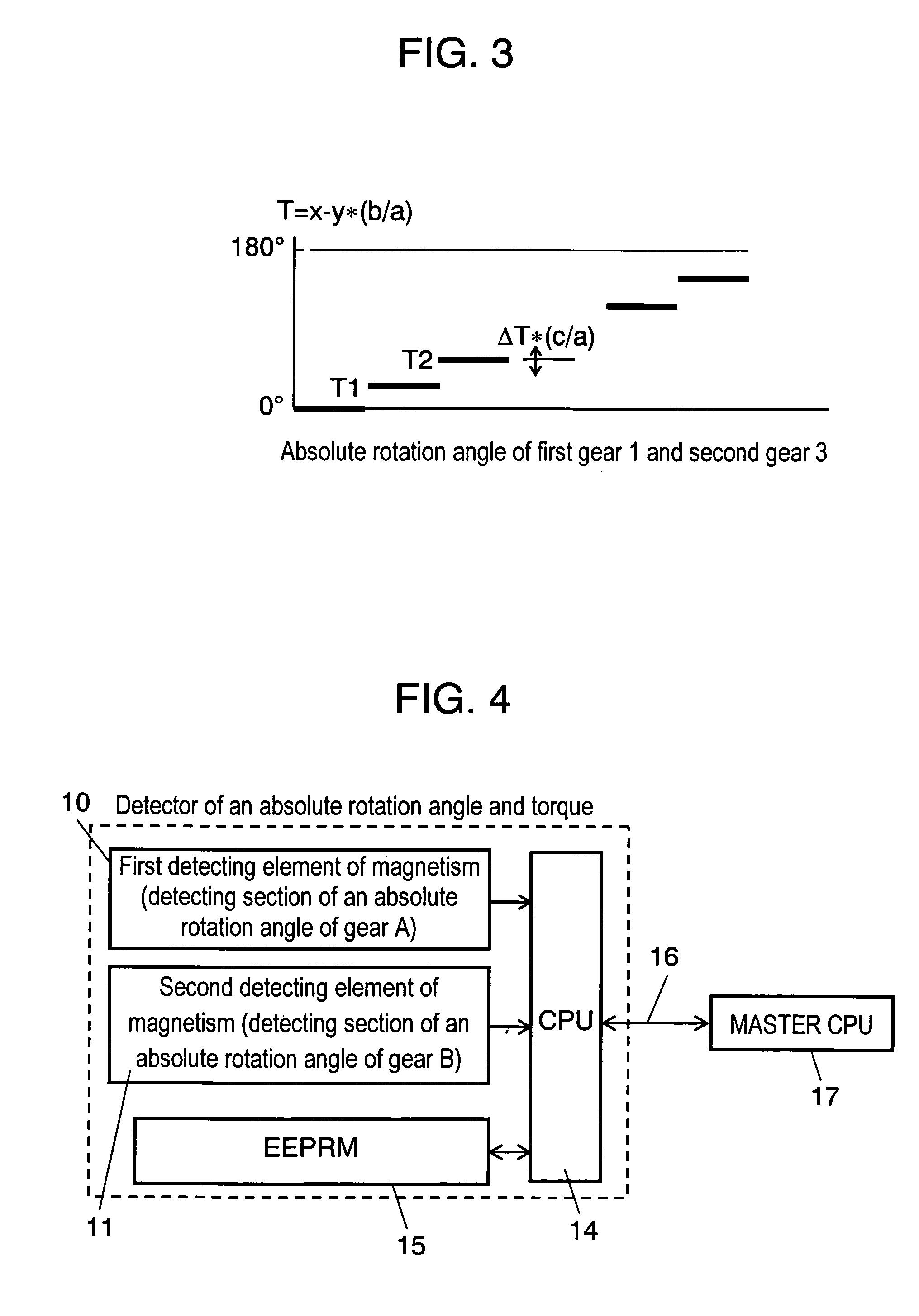
[0020]FIG. 1 shows a structure of a detector of an absolute rotation angle and torque in accordance with an exemplary embodiment of the present invention. A torsion-bar unit is formed of input shaft 2, torsion bar 5 and output shaft 4, wherein these elements are made of the same rigid body and placed concentrically. First gear 1 and second gear 3 are coupled to input shaft 2 and output shaft 4 respectively. First gear 1 engages with gear A6, and second gear 3 engages with gear B7. Gear A6 has first magnet 8 at its center, and gear B7 has second magnet 9 at its center. First magnet 8 and second magnet 9 are magnetized in one pole pair. Board 12 has first detecting element 10 of magnetism confronting first magnet 8, and board 13 has second detecting element 11 of magnetism confronting second magnet 9. First magnet 8 and first detecting element 10 form a first ...


PUM

PropertyMeasurementUnit
absolute rotation angleaaaaaaaaaa
torqueaaaaaaaaaa
absolute rotation anglesaaaaaaaaaa

Abstract

A detector of an absolute rotation angle and torque includes a first gear coupled to an input shaft of a torsion-bar unit, a gear A engaging with the first gear, and a first detecting section of an absolute rotation angle placed at the center of the gear A. The detector also includes a second gear coupled to an output shaft of the torsion-bar unit, a gear B engaging with the second gear, and a second detecting section of an absolute angle placed at the center of gear B.

Description

[0001]This application is a U.S. National Phase Application of PCT International Application PCT / JP04 / 012910.TECHNICAL FIELD[0002]The present invention relates to a detector, mounted to a torsion bar, for detecting an absolute rotation angle and torque simultaneously. The detector of the present invention is used in a power steering of cars.BACKGROUND ART[0003]FIG. 6 shows a conventional detector of a rotation angle and torque. Gear 18 is mounted to an input shaft (not shown) of a torsion bar. Gear 21 engaging with gear 18 includes round-shaped code plate 20 having numbers of magnetic poles. Code plate 20 rotates following the rotation of the input shaft. Detecting element 22 of magnetism counts the number of poles rotating, thereby detecting a rotation angle of the input shaft. Gear 42 is mounted to an output shaft (not shown) of the torsion bar, and detects a rotation angle of the output shaft in the same manner as discussed above. When torque works to the torsion bar, thereby pro...

Claims


Application Information

Patent Timeline
Patent Type & Authority Patents(United States)
IPC IPC(8): G01L3/00B62D5/04B62D5/06B62D6/10B62D15/02G01B7/00G01B7/30G01D5/14G01D5/16G01D5/245G01L3/10
CPCB62D6/10B62D15/0215B62D15/0245G01D5/145G01L3/101G01L3/104G01D2205/28G01D2205/26
Inventor OIKE, KOJIUEHIRA, KIYOTAKAUSHIHARA, MASAHARU
Owner PANASONIC CORP
Why Eureka
Try Eureka