Arrangement for preventing energy absorbing material degradation on draft gears

a technology of energy absorption material and arrangement, which is applied in the direction of draw-gear, railway coupling accessories, railway components, etc., can solve the problems of draft gear failure at a speed of over 8 miles per hour, coupler force approaching 1,000,000 pounds, and draft gear assembly failure, etc., to achieve more reliable operation

Inactive Publication Date: 2007-08-21
WESTINGHOUSE AIR BRAKE TECH CORP
View PDF8 Cites 13 Cited by
  • Summary
  • Abstract
  • Description
  • Claims
  • Application Information

AI Technical Summary

Benefits of technology

[0027]It is therefore one of the primary objects of the present invention is to provide a draft gear assembly which protects a railway car by absorbing shocks in both draft and buff conditions.
[0030]Additional object of the present invention is to provide a draft gear assembly with a front and rear elastomeric compressible resilient members having more reliable operation.
[0031]Yet additional object of the present invention is to provide economical means of retrofitting existing draft gear assemblies to limit compression of the front and rear elastomeric compressible resilient members.

Problems solved by technology

Testing of the Twin-Pac draft gears according to paragraphs 6.0 and 9.0 of AAR standard M-901G-00 and involving two 70-ton nominal capacity covered hopper cars loaded to maximum gross weight of 220,000 pounds with dry sand resulted in draft gears failure at a speed being over 8 miles per hour and coupler force approaching 1,000,000 pounds.
It has been determined that the draft gear assembly failure was due to over-compression of the elastomeric pad stacks.
However, the slackless type coupler does not utilize the yoke as disclosed in U.S. Pat. No. 6,446,820 and does not utilize the front resilient compression member to absorb impact energy in draft conditions.

Method used


Image

  • Arrangement for preventing energy absorbing material degradation on draft gears
  • Arrangement for preventing energy absorbing material degradation on draft gears
  • Arrangement for preventing energy absorbing material degradation on draft gears

Examples


Embodiment Construction

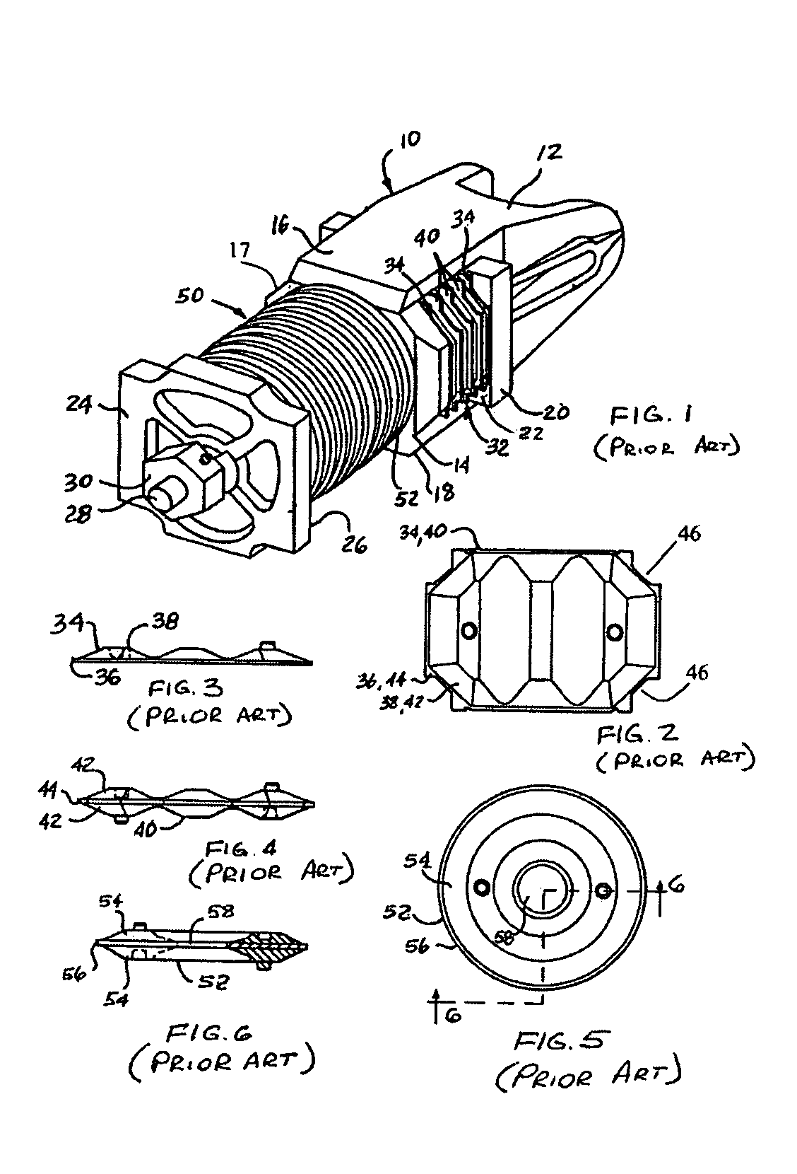
[0047]Prior to proceeding to the more detailed description of the present invention, it should be noted that for the sake of clarity identical components, having identical functions have been identified with identical reference numerals throughout the several views, which have been illustrated in the drawing figures.

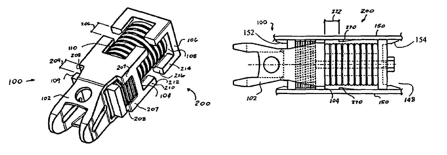
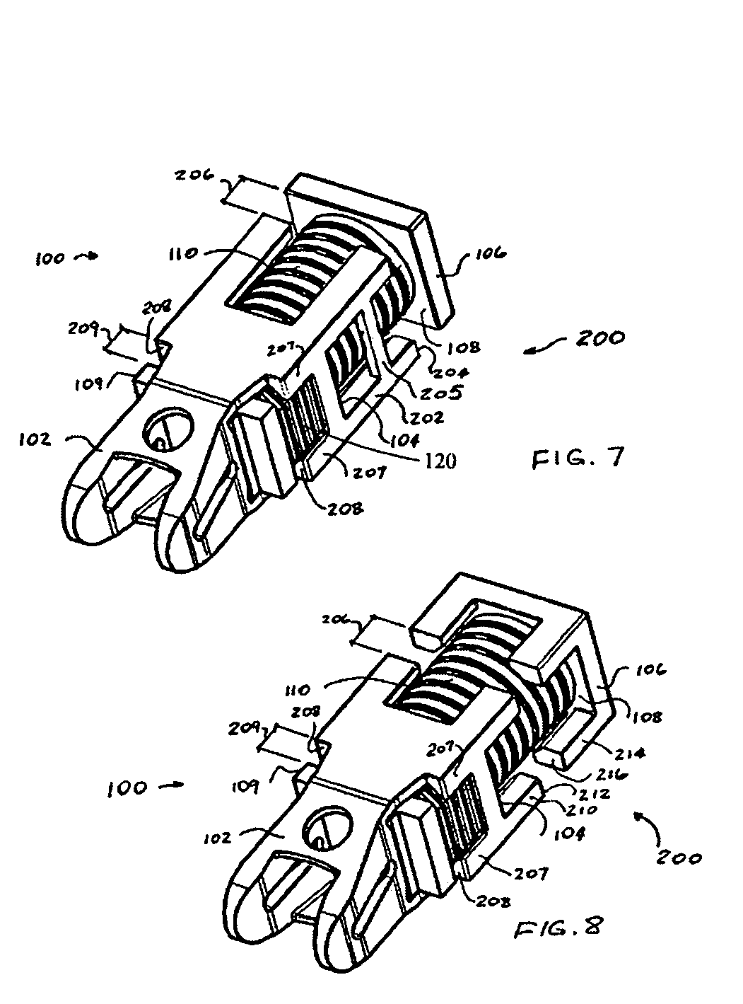
[0048]The draft gear assembly of the present invention overcomes the aforementioned disadvantages by incorporating overtravel protection means disposed within the draft gear assembly or attached to the side walls of the center sill of the railway car for enabling compression of the compressible resilient members that does not exceed predetermined full buff and draft travel distances.

[0049]The illustrated embodiments show that the draft gear assembly of the present invention may be used with standard E-couplers and rotary dump couplers, as well as with couplers having E coupler heads and F shanks, for example. For the sake of brevity, the following description will be con...


PUM


Abstract

A draft gear assembly includes a yoke and a coupler follower disposed within the yoke. A front compressible resilient member is disposed intermediate the yoke and the coupler follower. A rear compressible resilient member engages a back wall of the yoke at one end and engages a rear follower at a distal end. A center rod extends through the rear compressible resilient member and the rear follower and engages a shortening member. A plurality of stops members are attached to the back wall of the yoke for limiting compression of the rear compressible resilient member during buff travel. The stop members may be extended toward the coupler follower for limiting compression of the front compressible resilient member during draft travel. Alternatively, a center rod or elastomeric pads may be adapted for limiting compression of the resilient compressible members during buff and draft travel. Stops for limiting compression may be also attached to a center sill.

Description

CROSS-REFERENCE TO RELATED APPLICATIONS[0001]This application is closely related to U.S. Pat. No. 6,446,820 entitled “Railcar Draft Gear Assembly and System” and its disclosure is hereby incorporated by reference thereto.FIELD OF THE INVENTION[0002]The present invention relates, in general, to draft gear assemblies for use in absorbing both buff and draft shocks normally encountered by railway rolling stock during make-up and operation of a train consist on a track structure and, more particularly, this invention relates to a draft gear assembly using elastomeric resilient compression material for absorbing both buff and draft shocks.BACKGROUND OF THE INVENTION[0003]The following background information is provided to assist the reader to understand the environment in which the invention will typically be used. The terms used herein are not intended to be limited to any particular narrow interpretation unless specifically stated otherwise in this document.[0004]Draft gear assemblies ...

Claims


Application Information

Patent Timeline
Patent Type & Authority Patents(United States)
IPC IPC(8): B61G1/00
CPCB61G9/06B61G9/24
Inventor RING, MICHAEL E.SOMMERFELD, HOWARD
Owner WESTINGHOUSE AIR BRAKE TECH CORP
Why Eureka
Try Eureka