De-interlacing device and method therefor

a technology of interlacing device and interlacing method, which is applied in the direction of instruments, television systems, signal generators with optical-mechanical scanning, etc., can solve problems such as image flicker

Inactive Publication Date: 2007-08-21
HIMAX TECH LTD
View PDF4 Cites 30 Cited by
  • Summary
  • Abstract
  • Description
  • Claims
  • Application Information

AI Technical Summary

Benefits of technology

[0010]It is therefore an object of the invention to provide a de-interlacing device and a method therefor.
[0011]The invention achieves the above-identified object by providing a de-interlacing device being used for an image. The image includes at least one field, which includes a plurality of pixels arranged in an M*N matrix. The de-interlacing device is for determining a brightness value of the current pixel and includes a motion detector for determining whether or not the current pixel is motional, an edge detector for detecting an edge type of the current pixel if the current pixel is motional, and an edge-based de-interlacer, which comprises a reference pixel determiner for determining a plurality of edge reference pixels having the strongest correlation with the current pixel according to the edge type, and a brightness value determiner for determining the brightness value of the current pixel according to the edge reference pixels.
[0012]The invention also achieves the above-identified object by providing a de-interlacing method. First, it is determined whether or not the current pixel is motional. If the current pixel is motional, the edge type of the current pixel is detected. The current pixel can be classified as one of the edge types, that is, a smooth region, a vertical edge, a horizontal edge, and an inclined edge. Next, a plurality of edge reference pixels having the strongest correlation with the current pixel is determined according to the edge type. Finally, the brightness value of the current pixel is determined according to these edge reference pixels.

Problems solved by technology

However, the de-interlacing method mentioned above tends to cause the problem of image flicker.

Method used


Image

  • De-interlacing device and method therefor
  • De-interlacing device and method therefor
  • De-interlacing device and method therefor

Examples


Embodiment Construction

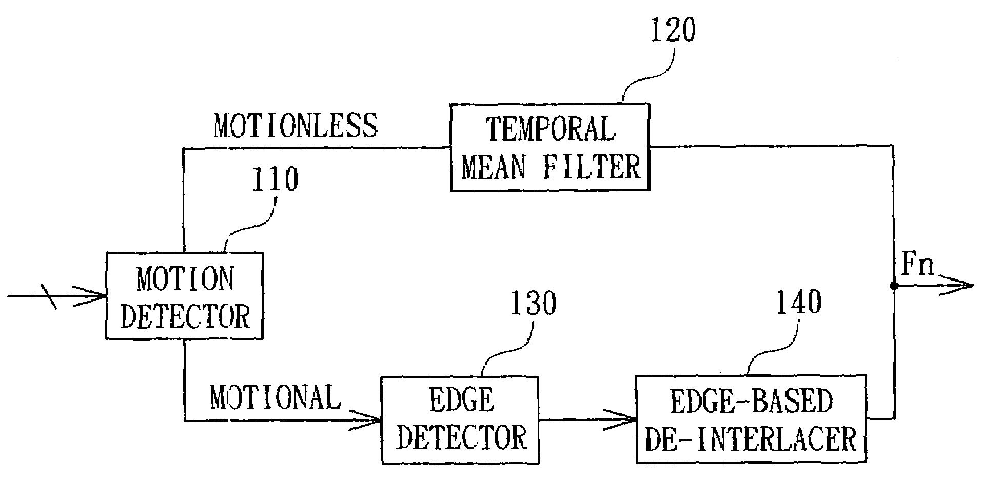
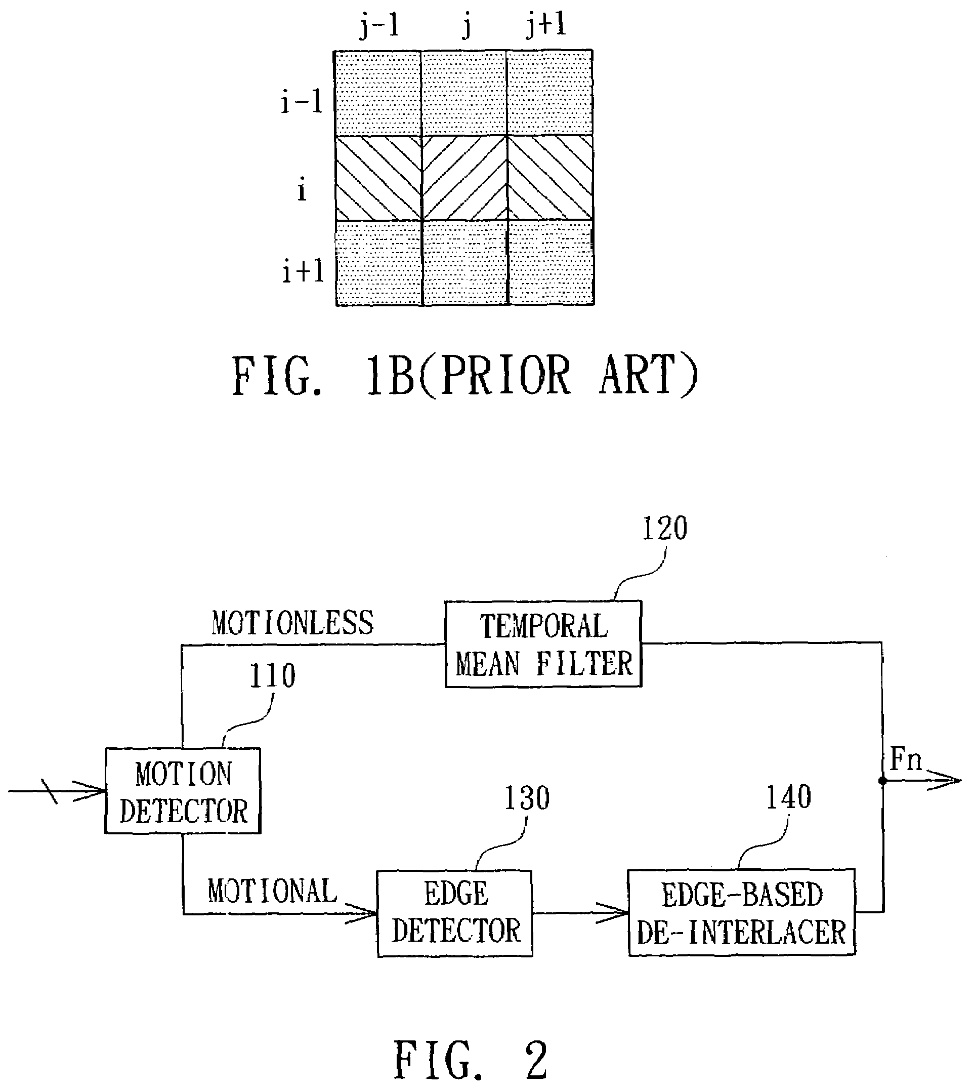
[0027]FIG. 2 is a block diagram showing a de-interlacing device according to a preferred embodiment of the invention. The de-interlacing device 100 includes a motion detector 110, a temporal mean filter 120, an edge detector 130, and an edge-based de-interlacer 140.

[0028]The motion detector 110 receives interlaced image data, and determines whether or not the interlaced image data is motional or motionless. If the interlaced image data is motionless, the interlaced image data is de-interlaced by the temporal mean filter 120; or otherwise processed by the edge detector 130. The motion detector 110 of this embodiment is to determine that each pixel belongs to the motion portion or motionless portion of the image. If the pixel belongs to the motion portion, it is passed to the edge detector 130; or otherwise to the temporal mean filter 120.

[0029]The temporal mean filter 120 de-interlaces the motionless pixel and then outputs the de-interlaced pixel. The manner for de-interlacing the mo...


PUM


Abstract

A de-interlacing device and method therefor for de-interlacing an image. The image includes at least one field, which includes a plurality of pixels arranged in an M*N matrix. The de-interlacing device is for determining the brightness value of a current pixel and includes the following elements. A motion detector is for determining whether or not the current pixel is motional. An edge detector detects an edge type of the current pixel if the current pixel is motional. An edge-based de-interlacer includes a reference pixel determiner for determining a plurality of edge reference pixels having the strongest correlation with the current pixel according to the edge type, and a brightness value determiner for deriving the brightness value of the current pixel according to the edge reference pixels.

Description

[0001]This application claims the benefit of provisional application Ser. No. 60 / 505,622, filed Sep. 25, 2003, and the benefit of Taiwan application Serial No. 92137852, filed Dec. 31, 2003, the subject matters of which are incorporated herein by reference.BACKGROUND OF THE INVENTION[0002]1. Field of the Invention[0003]The invention relates in general to a de-interlacing device and a method therefor, and more particularly to an edge-based de-interlacing device adapted to motion frames, and a method therefor.[0004]2. Description of the Related Art[0005]A film is generally shot and displayed in an interlaced manner. Taking the television as an example, the displaying of one frame is completed by firstly displaying an odd field thereof and then an even field thereof. The odd field is composed of the odd-numbered lines of the frame, and the even field is composed of the even-numbered lines of the frame.[0006]The typical television has a refresh rate of 30 Hz. That is, 30 frames are disp...

Claims


Application Information

Patent Timeline
Patent Type & Authority Patents(United States)
IPC IPC(8): H04N11/00H04N7/01G09G5/00G09G5/02H03M13/27H04N5/14H04N5/44
CPCG09G5/00H04N5/144H04N7/012G09G2310/0229G09G2320/0247G09G2320/0261
Inventor CHANG, FUNG-JANEHUANG, LING-SHIOUTAI, SHEN-CHUAN
Owner HIMAX TECH LTD
Why Eureka
Try Eureka