Armoire

a technology for armoires and dressing tables, applied in the field of armoires, can solve the problems of inability to expand a room or the remodeling of interior spaces, and achieve the effect of convenient opening

Inactive Publication Date: 2007-08-28
CRAFT JR LESTER R +1
View PDF29 Cites 32 Cited by
  • Summary
  • Abstract
  • Description
  • Claims
  • Application Information

AI Technical Summary

Benefits of technology

[0004]It is another objective of the present invention to provide a decorati

Problems solved by technology

Further, the addition of a room or the remodeling of interior space is often not feasible or practical.
Of particular inconvenie

Method used


Image

  • Armoire
  • Armoire
  • Armoire

Examples


Embodiment Construction

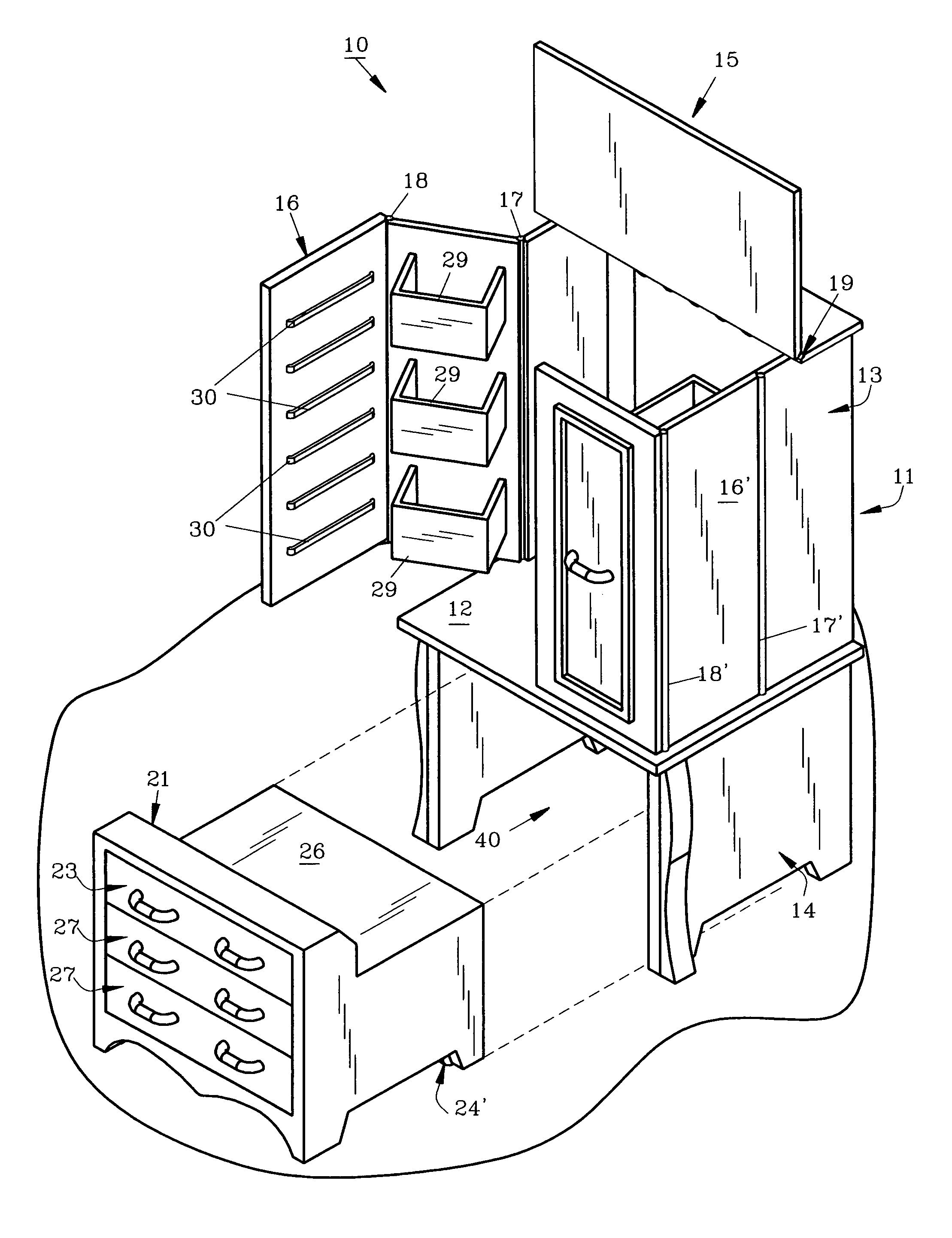
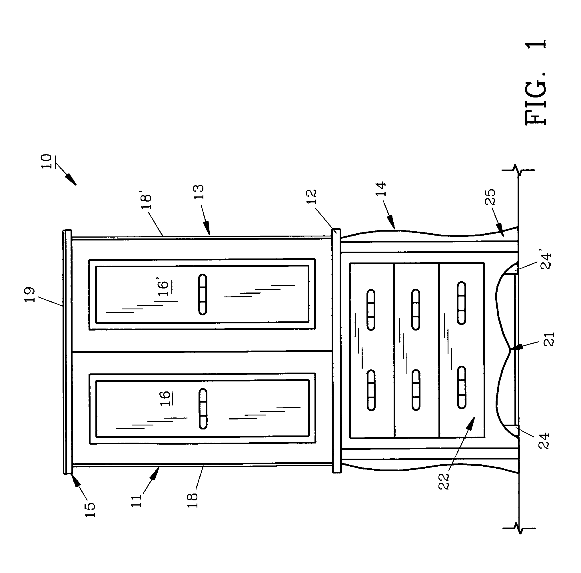
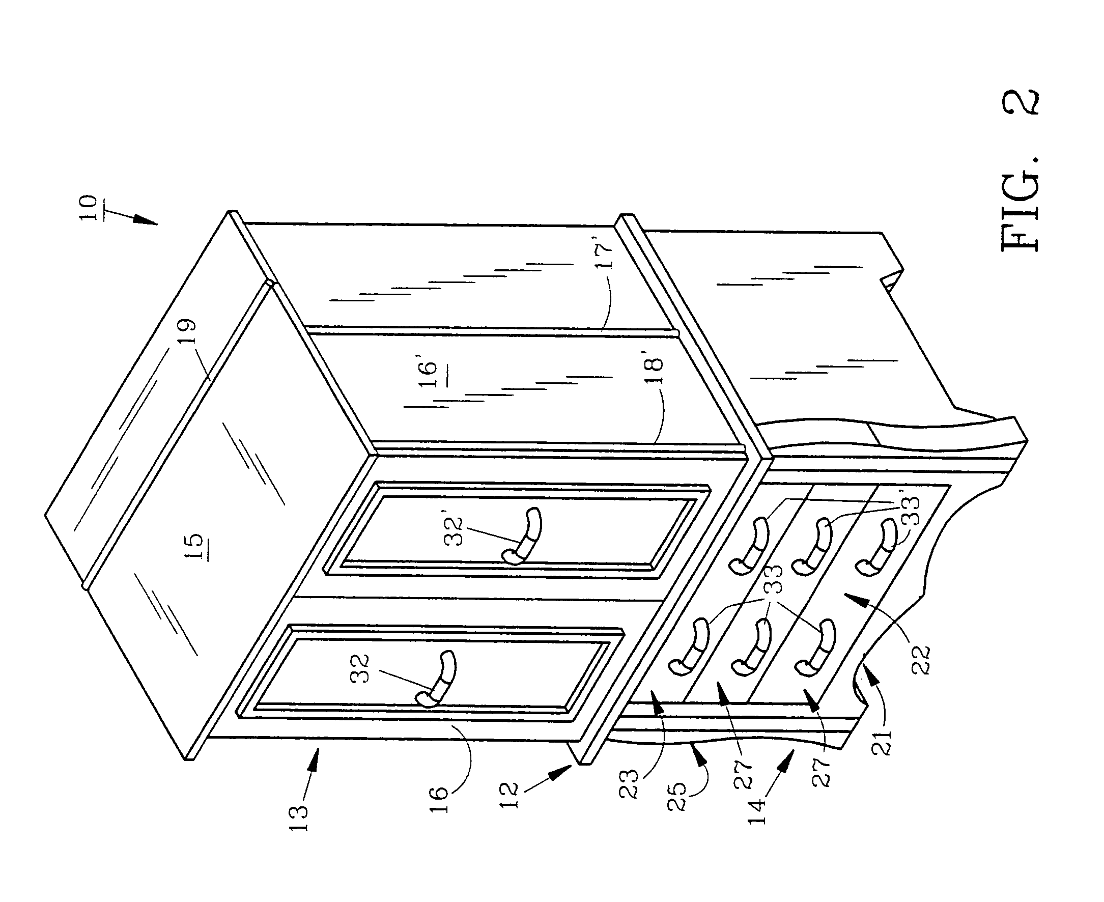
[0016]For a better understanding of the invention and its operation, turning now to the drawings, FIG. 1 illustrates a front view of preferred armoire 10 which includes an outer housing 11 divided by shelf 12 into upper section 13 and lower section 14. Housing 11 includes top 15 which is hingedly attached to upper section 13 along with left bi-foldable door 16, having hinges 17, 18 (FIGS. 3 and 4) and right bi-foldable door 16′, with hinges 17′, 18′ (FIGS. 3 and 4) as shown in FIGS. 1 and 2. As shown in FIGS. 2, 4 and 6 doors 16, 16′ include elongated handles 32, 32′ respectively.

[0017]In FIG. 3, armoire 10 is shown with door 16 open while door 16′ remains in a closed posture. Top 15 is raised in FIG. 3 from its closed position as seen in FIGS. 1, 2 and 6. Top hinge 19 allows top 15 to pivot near the back of cabinet upper section 13 as seen in FIG. 4. As further shown in FIG. 3, housing 11 forms cavity 40 for containing bench 21 in lower section 14. Bench 21 includes wheels 24, 24′ ...


PUM


Abstract

The armoire includes a concealed, removable bench containing two drawers. In use the bench is removed for seating purposes and the doors of the armoire are opened. A shelf is provided for various tasks such as for use as a make-up counter. A mirror on the inside of the upper section is equipped with lights. Shelves and other accessories contained within the upper section provide convenience for the user. When the armoire is dormant the bench is contained therein with the front of the bench flush with the housing to provide a normal appearance for the armoire.

Description

FIELD OF THE INVENTION[0001]The invention herein pertains to armoires and particularly pertains to an armoire having a removable bench contained within its lower section.DESCRIPTION OF THE PRIOR ART AND OBJECTIVES OF THE INVENTION[0002]With the floor space of houses, apartments and other dwellings being in greater demand in recent years, the need for additional dressing and personal cosmetic areas, bathrooms, closets and the like has increased. Further, the addition of a room or the remodeling of interior space is often not feasible or practical. Dwellers in rented houses and apartments are often forbidden from making structural changes to meet their specific, desired requirements. Of particular inconvenience is a situation in which two (2) or more people dressing or attending to cosmetic needs simultaneously use a single bathroom.[0003]Thus in view of the problems and disadvantages of smaller, conventional living areas, the present invention was conceived and one of its objectives ...

Claims


Application Information

Patent Timeline
IPC IPC(8): A47B81/00
CPCA47B46/00
Inventor CRAFT, JR., LESTER R.CRAFT, STACEY M.
Owner CRAFT JR LESTER R
Why Eureka
Try Eureka