Portable terminal apparatus

a terminal and portable technology, applied in the direction of loop antennas, radiating element structural forms, resonance antennas, etc., can solve the problems of limited antenna b>5/b> location in the portable terminal, difficult to locate the antenna b>5/b> with a sufficient communication efficiency, and antenna may become larg

Active Publication Date: 2007-09-04
FUJITSU CONNECTED TECH LTD
View PDF12 Cites 23 Cited by
  • Summary
  • Abstract
  • Description
  • Claims
  • Application Information

AI Technical Summary

Benefits of technology

[0013]It is a general object of the present invention to provide an improved and useful portable terminal apparatus in which the above-mentioned problems are eliminated.
[0014]A more specific object of the present invention is to provide a portable terminal apparatus which improves a communication efficiency while attempting a miniaturization of a housing.
[0016]According to the above-mentioned invention, the antenna can be made with a large loop form by being arranged to surround the battery that has a large size among component parts constituting the portable terminal apparatus. Additionally, although it is necessary to provided a predetermined space to allow the battery to be attached and detached, the antenna can be arranged in the space so as to surround the battery. Thus, if the antenna loop is made large, the portable terminal apparatus can be prevented from being enlarged.
[0019]According to the above-mentioned invention, the antenna can be positively arranged in the space surrounding the battery even if the space is small since the flat cable antenna is arranged upright to the bottom surface of the housing. Thus, the portable terminal apparatus is prevented from being enlarged due to arrangement of the antenna. Additionally, the size in a direction of the thickness of the portable terminal apparatus is not increased, even when the flat cable is upright to the bottom surface of the housing, if the width of the antenna is made smaller than the thickness of the battery.

Problems solved by technology

However, the whip antenna must protrude from the portable terminal apparatus even when the antenna is accommodated in the portable terminal apparatus, which may be a problem in portability.
However, in the above-mentioned conventional portable terminal apparatus 1, since the planer antenna 5, in which a spiral antenna wiring 11 is formed on the single base material 10, is used, there is a limitation arises in the location of the antenna 5 in the portable terminal apparatus 1.
For this reason, it is difficult to locate the antenna 5 with a sufficient communication efficiency, which may affect the communication function of the portable terminal apparatus 1.
Moreover, if it is attempted to provide a high communication efficiency to the conventional antenna 5, the antenna may become large, which requires a space to accommodate the enlarged antenna 5.
Accordingly, there is a problem that the size of the portable terminal apparatus 1 increases.

Method used


Image

  • Portable terminal apparatus
  • Portable terminal apparatus
  • Portable terminal apparatus

Examples


Embodiment Construction

[0034]A description will now be given, with reference to the drawings, of a preferred embodiment according to the present invention.

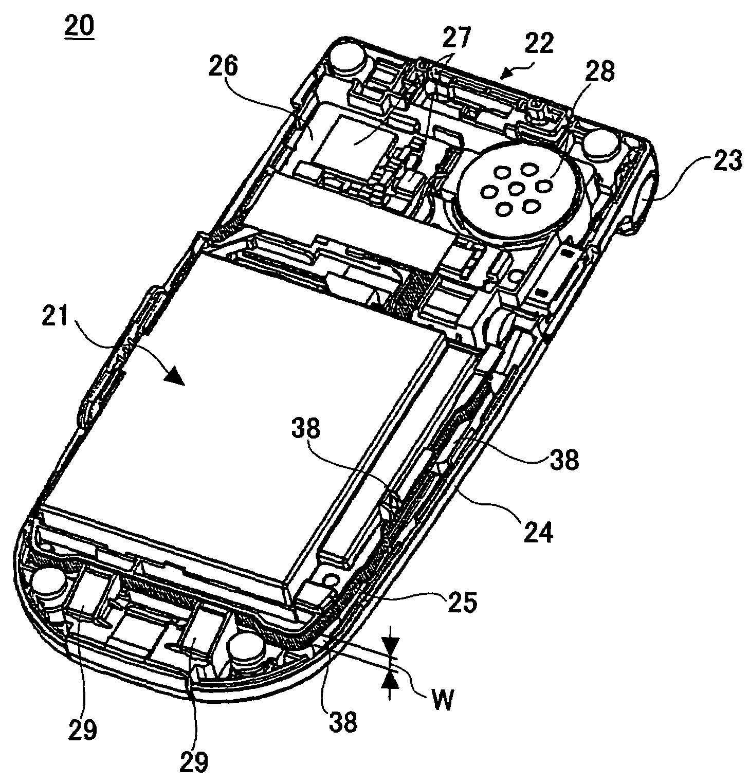
[0035]FIGS. 4 through 6 show a portable terminal apparatus 20 according to an embodiment of the present invention. The portable terminal apparatus 20 according to the present embodiment is a flip type cellular phone. FIG. 4 is a perspective diagram of the portable terminal apparatus 20 viewed from a bottom side, wherein a bottom plate of a housing 24 is removed so as to show an internal structure. FIG. 5 is a cross-sectional view of a body part 22, which constitutes the portable terminal apparatus 20, taken along a line A2-A2 of FIG. 6. It should be noted that the portable terminal apparatus 20 comprises the body part 22 and a lid part (usually provided with a liquid crystal display device or the like). However, since the present invention relates to the body part 22, an illustration of the lid part is omitted in each figure and the body part 22 is sole...


PUM


Abstract

A portable terminal apparatus can improve a communication efficiency while attempting a miniaturization of a housing. The portable terminal apparatus has a housing that accommodates component parts therein. An antenna and a battery are accommodated in the housing. The antenna is arranged so as to surround the battery.

Description

BACKGROUND OF THE INVENTION[0001]1. Field of the Invention[0002]The present invention relates to portable terminal apparatuses and, more particularly, to a portable terminal apparatus equipped with an antenna.[0003]2. Description of the Related Art[0004]In recent years, a mobile communications technology is quickly developed and the portable terminal or personal digital assistant equipment as represented by a cellular phone has become popular rapidly. Since the portable terminal has become connectable with the Internet, a strong demand has been made by users to enlarge a liquid crystal display device incorporated in the portable terminal apparatus. For this reason, the personal digital assistant equipment of a fold-up or flip type has become widely used. The flip type portable terminal has a body part having operational keys such as ten keys and a lid part that is connected to the body part and provided with a liquid crystal display device.[0005]The portable terminal apparatus is re...

Claims


Application Information

Patent Timeline
Patent Type & Authority Patents(United States)
IPC IPC(8): H01Q1/24H01Q1/00H01Q1/38H01Q7/00H04M1/02
CPCH01Q1/243H01Q1/38H01Q7/00
Inventor FUJII, SHIGEHIROHIRABAYASHI, YOSHIHIROADACHI, KATSUMIFURUKI, KEN-ETSUSHIN, TAKAHIROONO, YOSHIHIRO
Owner FUJITSU CONNECTED TECH LTD
Why Eureka
Try Eureka