Horizontal surface plasmon resonance instrument with improved light path

Inactive Publication Date: 2007-09-04
WISCONSIN ALUMNI RES FOUND
View PDF11 Cites 22 Cited by
  • Summary
  • Abstract
  • Description
  • Claims
  • Application Information

AI Technical Summary

Benefits of technology

[0008]The present invention provides a surface plasmon resonance instrument with a horizontal sensing surface but with an optical mechanism that allows the light source and camera to be placed horizontally on eit

Problems solved by technology

Current surface plasmon resonance (SPR) equipment can be bulky and difficult to use.
Typically, the sensing surface is oriented vertically, which allows ready access to the optical system for such adjustment, but this vertical orientation can cause problems sealing the flow cells ho

Method used


Image

  • Horizontal surface plasmon resonance instrument with improved light path
  • Horizontal surface plasmon resonance instrument with improved light path
  • Horizontal surface plasmon resonance instrument with improved light path

Examples


Embodiment Construction

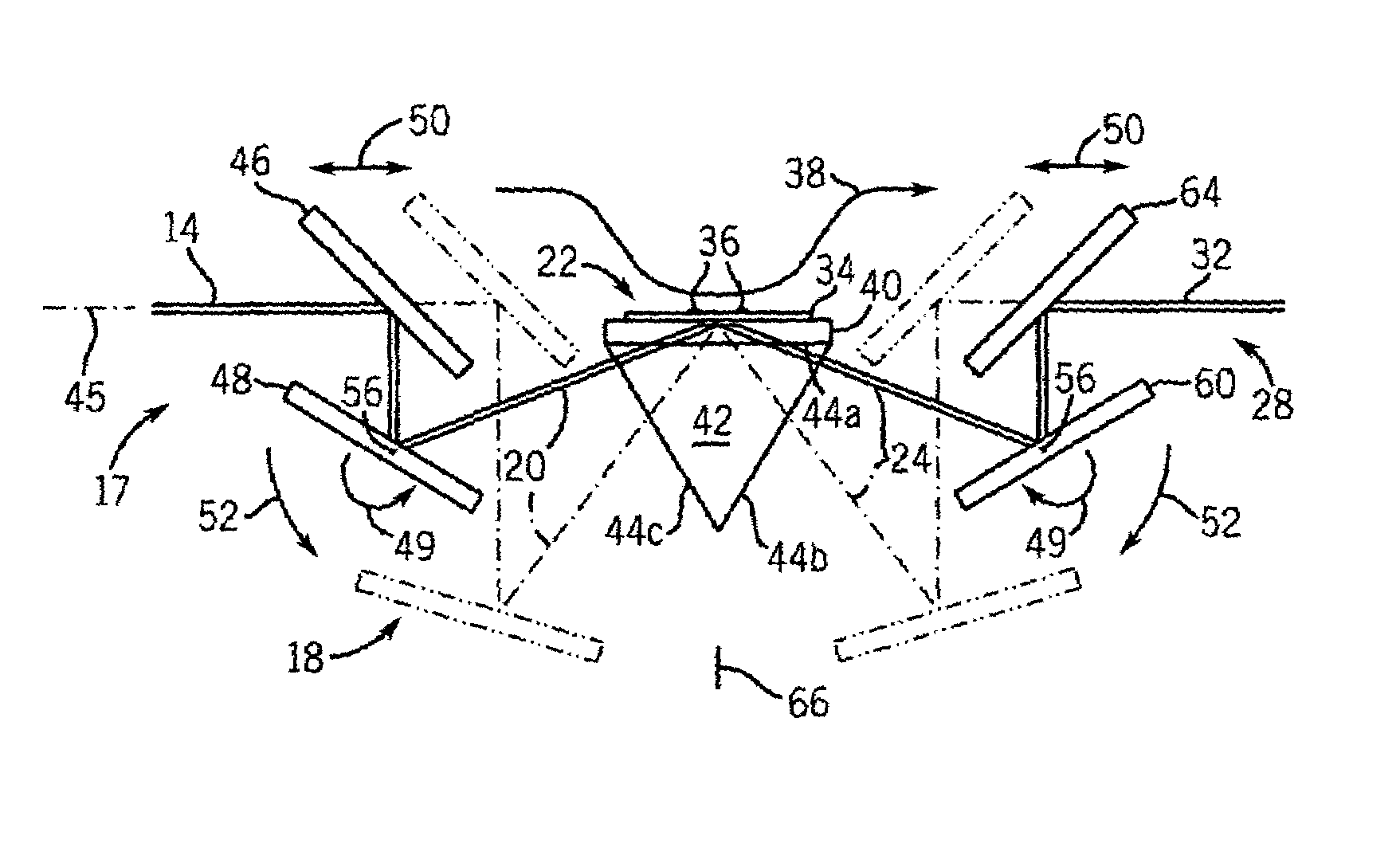
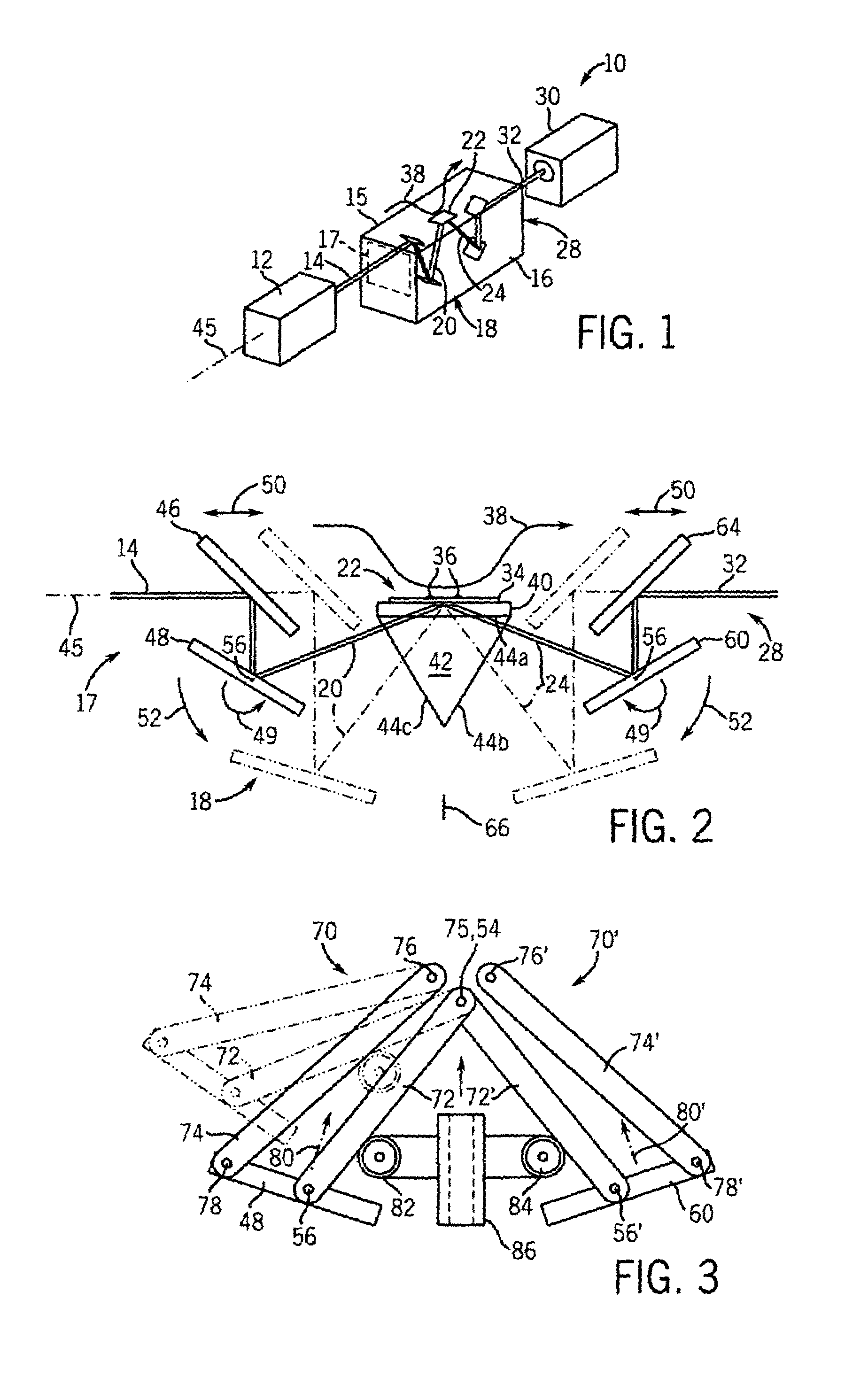
[0039]Referring now to FIG. 1, a horizontal surface plasmon resonance instrument (HSPR) 10, works with a light source 12 providing an analyzing light beam 14 to the analyzer unit 15 where it is modified to become modified light beam 32 and received by camera 30. Both analyzing light beam 14 and modified light beam 32 are coaxial along fixed horizontal axis 44 allowing the light source 12 and camera 30 to be fixed and mounted conveniently to either side of the analyzer unit 15.

[0040]The light source 12 may be, for example, a monochromatic coherent or incoherent source including a lamp or laser, filter, polarizer, and lens system of types well known in the art. The light source directs the analyzing light beam 14 toward the analyzer unit where the analyzing light beam 14 enters an entrance area 17 to be received by the optical assembly 18 held by a support frame 16 of the analyzer unit 15. The optical assembly 18 redirects the analyzing light beam 14 to create a first incident beam 20...


PUM


Abstract

A surface plasmon resonance imaging apparatus provides an improved optical assembly allowing fixed source and detector operating with a horizontal test surface for a more compact design. In a preferred embodiment, a mechanical linkage of planar mirrors provides a single point adjustment of angle of incidence and angle of refraction while maintaining a constant optical axis of the source and detector.

Description

CROSS-REFERENCE TO RELATED APPLICATIONS[0001]This application is a continuation-in-part of U.S. application Ser. No. 10 / 411,583 filed Apr. 10, 2003 now U.S. Pat. No. 7,148,968 hereby incorporated by reference.STATEMENT REGARDING FEDERALLY SPONSORED RESEARCH OR DEVELOPMENT[0002]This invention was made with United States government support awarded by the following agency: DOD ARPA F30602-01-2-0555. The United States has certain rights in this invention.BACKGROUND OF THE INVENTION[0003]The present invention relates to instruments for chemical and biological analyses employing surface plasmon resonance and, in particular, to an instrument having an improved light path that may be easily adjusted.[0004]In surface plasmon resonance, a sensor comprised of a thin metallic film is illuminated by light of an appropriate wavelength and angle of incidence on a “reflecting” side of the film. The energy from the light couples to electrons of the metal of the film creating a resonant condition (su...

Claims


Application Information

Patent Timeline
IPC IPC(8): G01N21/55
CPCG01N21/553
Inventor CODNER, ERIC P.CORN, ROBERT M.
Owner WISCONSIN ALUMNI RES FOUND
Why Eureka
Try Eureka