Lacing system for a shoe

a technology of lacing system and shoe, which is applied in the direction of shoe lacing hooks, shoe lace fastenings, accessories, etc., to achieve the effect of simple design and preventing any backsliding of the tension means

Inactive Publication Date: 2007-09-11
ATOMIC AUSTRIA
View PDF12 Cites 62 Cited by
  • Summary
  • Abstract
  • Description
  • Claims
  • Application Information

AI Technical Summary

Benefits of technology

[0006]This objective is achieved by the invention due to the fact that in a first tensioning region extending across the ankle region, the looping means lie more or less opposite one another and in another tensioning region extending in the direction towards the entry opening, the looping means are offset from one another in height on the wall regions, and the tensioning means in the first tensioning region forms a tensioning loop transversely spanning the shoe cut-out in a zigzag pattern between the looping means, of which a tensioning means cord spanning the shoe cut-out in a zigzag pattern between the looping means forms the other the other tensioning region and one end of the tensioning means cord is joined to the shoe by means of the fixing device in the region of the entry opening in a clamped and / or releasable arrangement. The surprising advantage of this approach is that tensioning forces can be uniformly distributed over a longer length of a shoe cut-out and tightening and loosening can be effected very rapidly and using one hand only.
[0008]Another embodiment is also possible in which the end region of the tensioning means provided with the threading loop is disposed between the first tensioning region and the other tensioning region, the advantage of which is that it results in bending elasticity to permit movement of the joints in the transition region.
[0009]In one possible embodiment of the lacing system, the looping means are provided in the form of tape loops on the shoe, e.g. made from textile or plastic strips, thus resulting in a design that is technically simple and inexpensive to produce.
[0010]The fact that the looping mean are plastic injection-moulded parts makes insertion of the tensioning means particularly easy and is gentler on the looped areas.
[0013]The fact that the anti-backsliding element for looping the tension means has a free-running region and a clamping region adjoining it means that the tensioning means can be simply moved away from the direction of tension in the direction towards the fixing means in order to clamp it, without requiring any other technical devices, thereby preventing any backsliding of the tension means which might otherwise loosen the clamping effect.
[0014]Finally, advantages are to be had from another embodiment of the lacing system in which the anti-backsliding element is provided in the form of a loop clamping eyelet, because strong retaining forces can be achieved for tensioning purposes and the demands placed on the fixing means in terms of securing the tensioning force are reduced and enable simple designs to be used.

Problems solved by technology

However, it is still necessary to use two hands to tie a knot in the two cords of the shoe lace.

Method used


Image

  • Lacing system for a shoe
  • Lacing system for a shoe
  • Lacing system for a shoe

Examples


Embodiment Construction

[0018]Firstly, it should be pointed out that the same parts described in the different embodiments are denoted by the same reference numbers and the same component names and the disclosures made throughout the description can be transposed in terms of meaning to same parts bearing the same reference numbers or same component names. Furthermore, the positions chosen for the purposes of the description, such as top, bottom, side, etc, relate to the drawing specifically being described and can be transposed in terms of meaning to a new position when another position is being described. Individual features or combinations of features from the different embodiments illustrated and described may be construed as independent inventive solutions or solutions proposed by the invention in their own right.

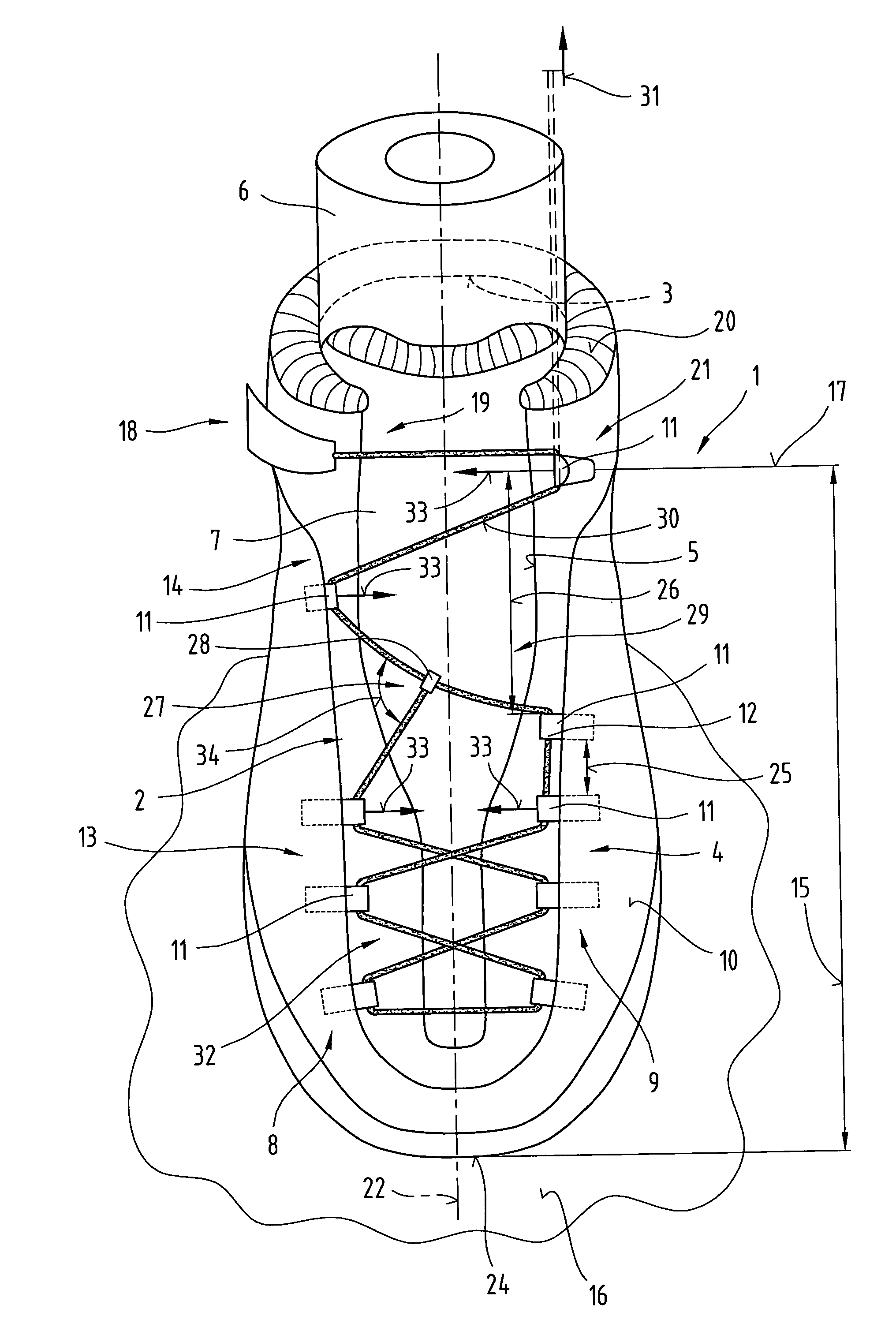
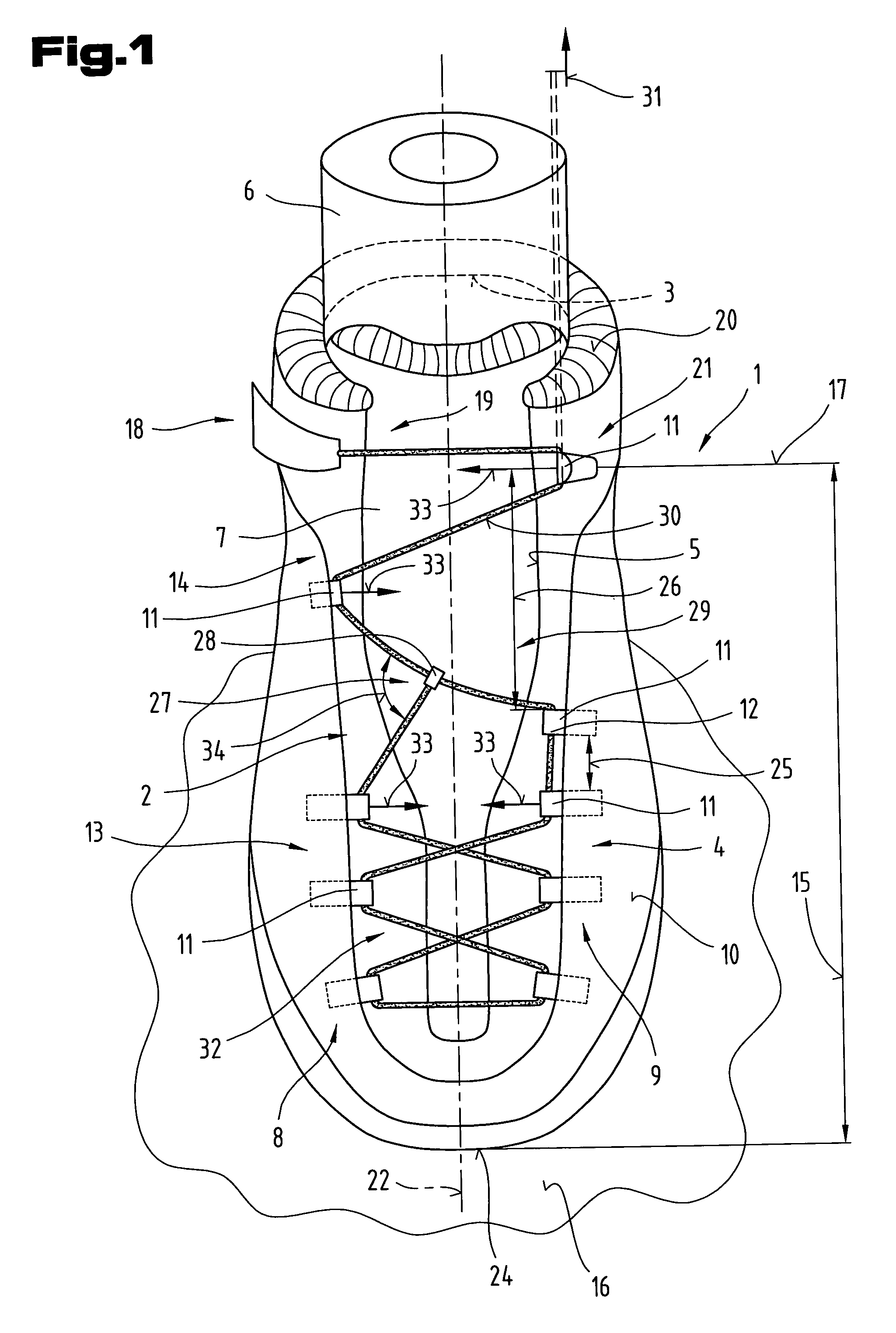
[0019]FIG. 1 illustrates a shoe 1 with a lacing system 2 for a shoe cut-out 5 extending from an entry opening 3 as far as an ankle region 4.

[0020]A shoe 1 of this type might be a lightweight s...


PUM


Abstract

The invention relates to a lacing system (2) for a shoe (1), in particular for an inner shoe, with a cord-type or lace-type tensioning means (12) and looping means (11) for the tensioning means (12) arranged on oppositely lying wall regions (8, 9) of a shoe cut-out (5) extending from an entry opening (3) approximately to as far as an ankle region (4) and having at least one fixing means (18) for the tensioning means (12). In a first tensioning region (13) extending across the ankle region (4), the looping means (11) are arranged more or less opposite one another and in another tensioning region (14) extending in the direction towards the entry opening (3), the looping means (11) are arranged offset in height from one another on the oppositely lying wall regions (8, 9) and the tensioning means (12) in the first tensioning region (13) forms a tensioning loop (32) zigzaging over the shoe cut-out (5), from which a tensioning means cord (30) spanning the shoe cut-out (5) in a zigzag pattern between the looping means (11) forms the other tensioning region (14), and an end region (19) of the tensioning means cord (30) is joined to the shoe (1) by means of the fixing device (18) disposed in the region of the entry opening (3) in a clamped and / or releasable arrangement.

Description

BACKGROUND OF THE INVENTION[0001]1. Field of the Invention[0002]The invention relates to a lacing system for a shoe, in particular an inner shoe, with a cord-type or lace-type tensioning means and looping means for the tensioning means disposed on oppositely lying wall regions of a cut-out in the shoe extending from an entry opening to approximately as far as an ankle region, and having at least one fixing means for the tensioning means.[0003]2. The Prior Art[0004]Patent specification EP 0 398 303 A2 discloses a clamping device for a lacing system of a shoe, in which different looping mean wall regions of a shoe cut-out and the shoe lace spans the shoe cut-out in a crossing arrangement between the looping means. During lacing, looping eyelets are provided so that the shoe lace can be threaded through freely. The looping means are provided in the form of tightening eyelets specifically in a transition region between an ankle region and the leg region and in the region of an entry ope...

Claims


Application Information

Patent Timeline
Patent Type & Authority Patents(United States)
IPC IPC(8): A43C11/00A43B11/00A43C1/00A43C3/00A43C7/00
CPCA43C1/00A43C3/00A43C7/00A43C1/06
Inventor HOLZER, HELMUTTRINKAUS, GERHARD
Owner ATOMIC AUSTRIA
Why Eureka
Try Eureka