
Ratchet wrench having two driving torques

Active Publication Date: 2007-09-11
LAI CHUN CHOU
View PDF8 Cites 54 Cited by
  • Summary
  • Abstract
  • Description
  • Claims
  • Application Information

AI Technical Summary

Benefits of technology

[0013]The other objective of the present invention is to provide a ratchet wrench including a simplified structure for allowing the two driving assemblies or devices of the ratchet wrench to be easily used to drive the fasteners with different driving torques without additional control member and / or the rotating wheel and / or the control knob.
[0015]The first latching device includes a seat disposed in the compartment of the rotor, and a spring member engaged between the pawl and the seat for biasing the tooth of the pawl to engage with the inner gear of the head and for allowing the rotor to be selectively rotated by the head of the tubular member either in an active driving direction or in a reverse direction. The seat of the first latching device includes no teeth formed thereon for preventing from influencing the driving operation of the rotor by the head of the tubular member.
[0019]The rotor includes a non-circular bore formed therein for slidably receiving a driving stem, the driving stem includes a non-circular cross section for engaging with the non-circular bore of the rotor and for allowing the driving stem to be rotated by the rotor. The rotor includes a space formed therein and communicating with the non-circular bore thereof for forming two inner peripheral shoulders in the rotor, the driving stem includes a spring-biased projection engaged in the space of the rotor and engageable with the inner peripheral shoulders of the rotor for limiting the driving stem to slide relative to the rotor and for preventing the driving stem from being disengaged from the rotor.

Problems solved by technology

However, the driving gear or cartridge may only be rotated or driven by the enlarged head of the handle for a single output torque but may not be rotated or driven by the enlarged head of the handle with different output torques.
However, similarly, the driving gear or cartridge may only be rotated or driven by the enlarged head of the handle for a single output torque but may not be rotated or driven by the head of the handle with different output torques.
However, a complicated control member and a rotating wheel are further required to be provided for engaging with the pawls in order to control the engagement between the drive member and the ratchet wheels or the engagement between the drive member and the internal gear of the enlarged head of the handle.

Method used


Image

  • Ratchet wrench having two driving torques
  • Ratchet wrench having two driving torques
  • Ratchet wrench having two driving torques

Examples


Embodiment Construction

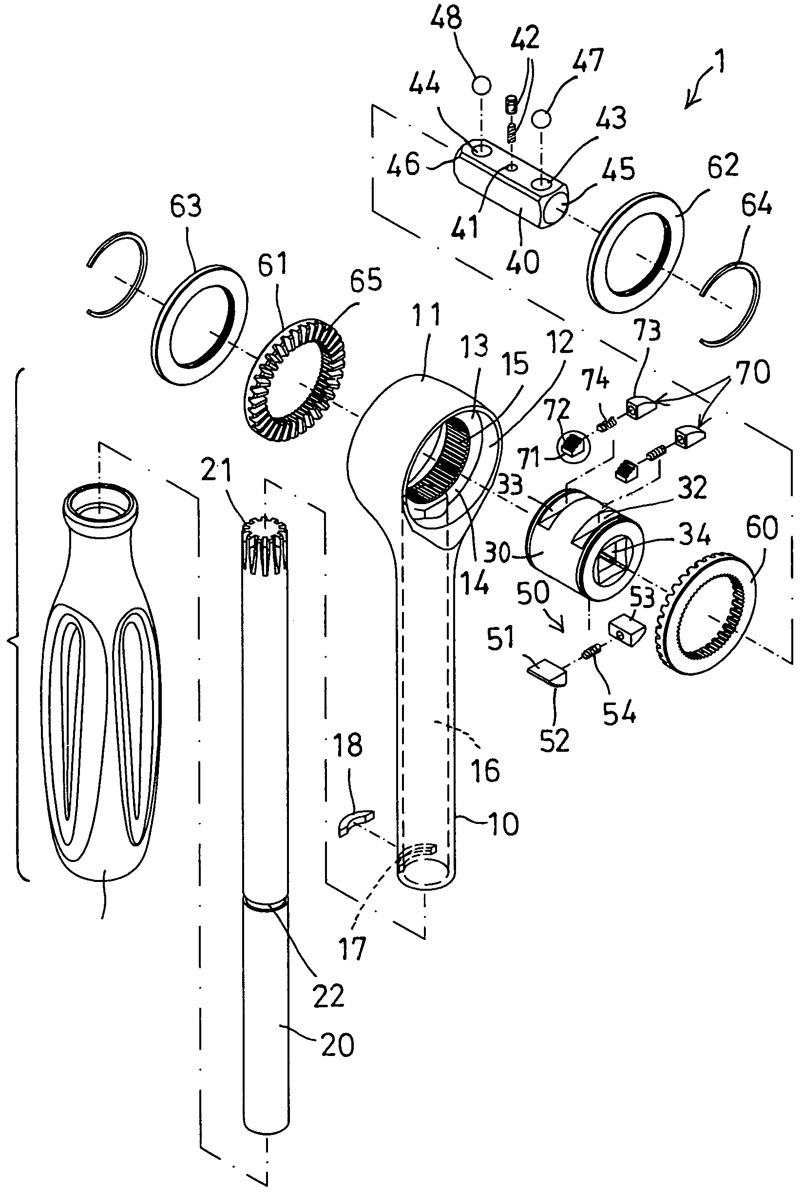
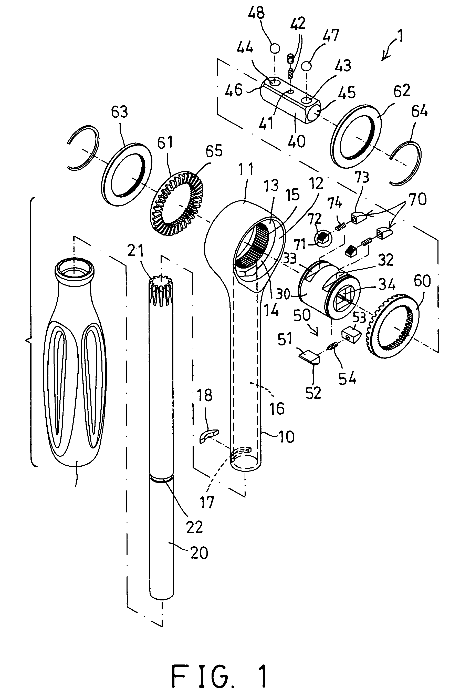
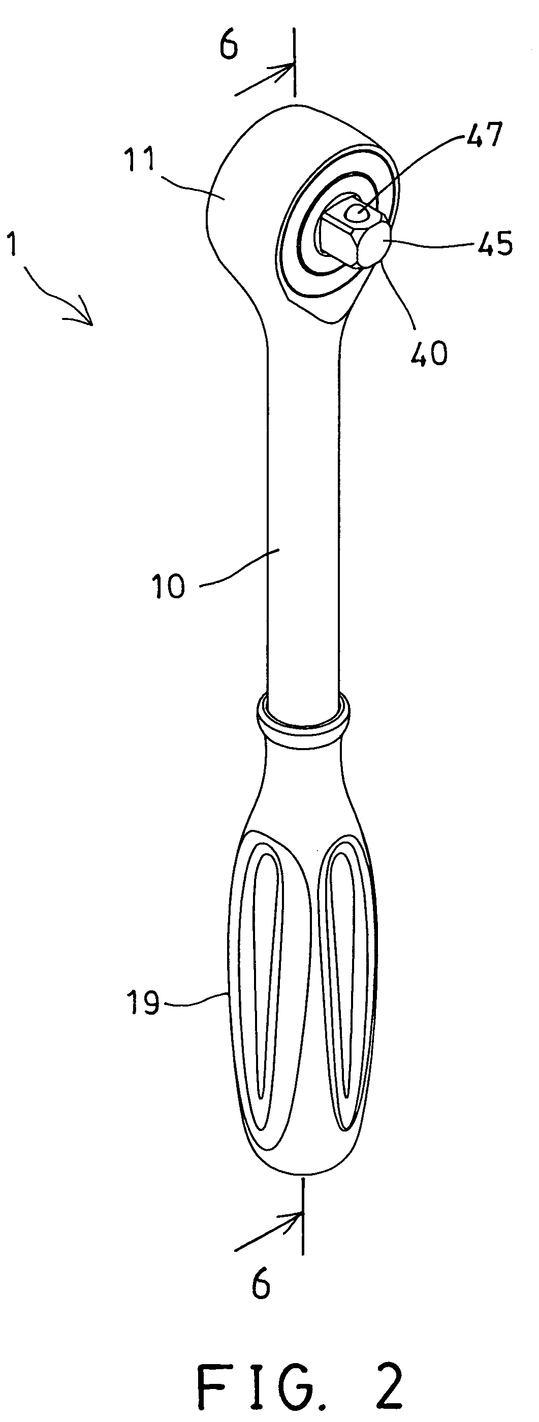
[0032]Referring to the drawings, and initially to FIGS. 1-6, a ratchet wrench 1 in accordance with the present invention comprises a longitudinal and / or tubular member 10 including an enlarged head 11 formed or provided on one end thereof, in which the head 11 includes a chamber 12 formed therein and includes a peripheral swelling 13 extended radially into the chamber 12 thereof for forming two opposite inner peripheral shoulders 14 between the head 11 and the peripheral swelling 13 and at two opposite sides of the peripheral swelling 13. The head 11 further includes an inner gear 15 formed or provided therein, such as provided on the inner peripheral portion of the peripheral swelling 13. The tubular member 10 further includes a longitudinal conduit 16 formed therein and partially formed into the peripheral swelling 13 for communicating with the chamber 12 of the head 11, best shown in FIGS. 1, 3 and 10.

[0033]A longitudinal drive shaft 20 is rotatably received in the longitudinal c...


PUM


Abstract

A ratchet wrench includes a tubular member having an inner gear formed in a head, a rotor rotatably received in the head and having a compartment aligned with the inner gear for receiving a stronger latching device, two ratchet wheels rotatably received in the head, two weaker latching devices disposed in the rotor and each having a spring-biased pawl for engaging with the ratchet wheels and for controlling the driving direction of the rotor by the ratchet wheels. A drive shaft is rotatably received in the tubular member and includes a driving gear for engaging with the ratchet wheels and for controlling the driving direction of the rotor by the ratchet wheels.

Description

BACKGROUND OF THE INVENTION[0001]1. Field of the Invention[0002]The present invention relates to a ratchet wrench, and more particularly to a ratchet wrench including two driving assemblies or devices for allowing the ratchet wrench to drive the fasteners with different driving torques.[0003]2. Description of the Prior Art[0004]Typical ratchet wrenches comprise a driving gear or cartridge rotatably received in an enlarged head of a handle, and a pivotal pawl attached to the driving gear or cartridge and engageable with an internal gear of the enlarged head of the handle for controlling the driving directions of the driving gear or cartridge by the enlarged head of the handle.[0005]For example, U.S. Pat. No. 5,960,680 to Chen et al. discloses one of the typical ratchet wrenches comprising a reversing disc coupled to the pivotal pawl for actuating the pivotal pawl to selectively engage with the internal gear of the enlarged head of the handle in order to control the driving directions...

Claims


Application Information

Patent Timeline
IPC IPC(8): B25B17/00B25B13/46
CPCB25B13/465B25B13/467B25B17/00B25B23/0035
Inventor LAI, CHUN CHOU
Owner LAI CHUN CHOU
Features
  • Generate Ideas
  • Intellectual Property
  • Life Sciences
  • Materials
  • Tech Scout
  • Unparalleled Data Quality
  • Higher Quality Content
  • 60% Fewer Hallucinations
Learn More