Vehicular headlamp

a technology of vehicular headlamps and headlamps, which is applied in fixed installation, lighting and heating apparatus, transportation and packaging, etc., can solve the problems of difficult to reduce the size and weight of actuators, the cutting-off line of low beam distribution patterns tends to change, and the driving force required of actuators for rotating the moveable shade also has to be somewhat large. , to achieve the effect of reducing the size, weight and cost of actuators

Inactive Publication Date: 2007-09-11
KOITO MFG CO LTD
View PDF3 Cites 10 Cited by
  • Summary
  • Abstract
  • Description
  • Claims
  • Application Information

AI Technical Summary

Benefits of technology

[0011]Accordingly, the object of the present invention to provide a projector type vehicular headlamp that includes a moveable shade and reduces the size, weight and cost of an actuator without having any detrimental impact on the formation of a low beam distribution pattern.

Problems solved by technology

As a result, the upper end edge of the moveable shade tends to wobble due to the vibrations of the vehicle, etc., and thus the position of the cut-off line of the low beam distribution pattern tends to change.
As a result, the driving force required from the actuator for rotating the moveable shade also has to be somewhat large.
This in turn makes it difficult to reduce the size and weight of the actuator and to reduce the cost.
Difficulties similar to the above occur not only when switching from the low beam distribution pattern to the high beam distribution pattern but also when switching from the low beam distribution pattern to an intermediate distribution pattern (which is an intermediate distribution pattern that is between the low beam distribution pattern and the high beam distribution pattern).

Method used


Image

  • Vehicular headlamp
  • Vehicular headlamp
  • Vehicular headlamp

Examples


Embodiment Construction

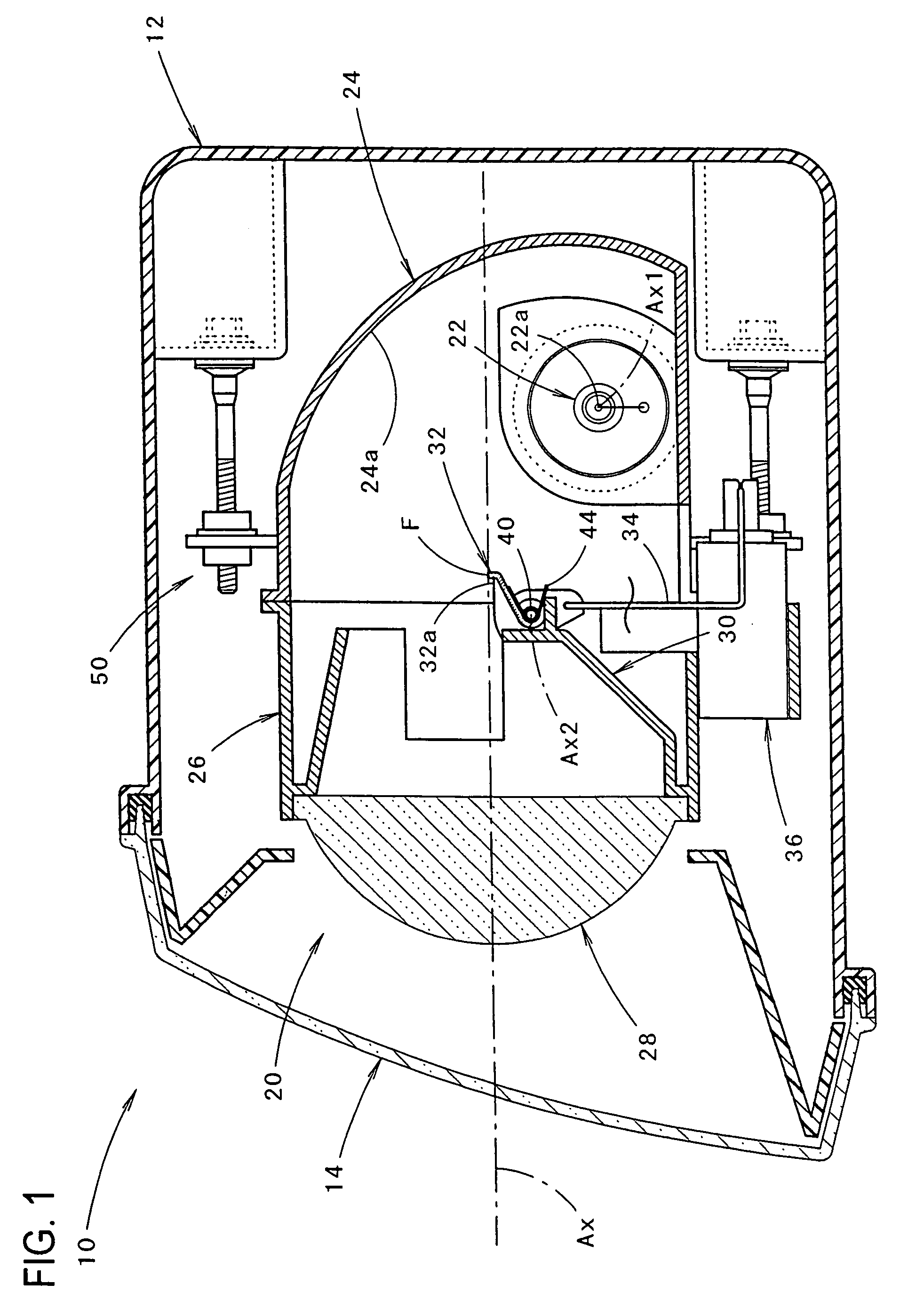
[0042]As seen from FIG. 1, the vehicular headlamp 10 of the present invention is comprised of a lamp body 12, a translucent cover 14, a lamp unit 20, and an aiming mechanism 50. The translucent cover 14 is generally plain and is attached to the front end opening of the lamp body 12. The lamp unit 20 has an optical axis Ax that extends in the longitudinal (front-rear) direction of a vehicle on which the headlamp 10 is mounted. The lamp unit 20 is housed in a lamp chamber formed by the lamp body 12 and the translucent cover 14, and it is tiltable in the vertical direction and the lateral direction by the aiming mechanism 50.

[0043]When adjustment of the aiming direction of the lamp unit 20 using the aiming mechanism 50 is completed, the optical axis Ax of the lamp unit 20 is oriented or faces in a direction that is approximately 0.5 to 0.6° downward with respect to the longitudinal direction of the vehicle.

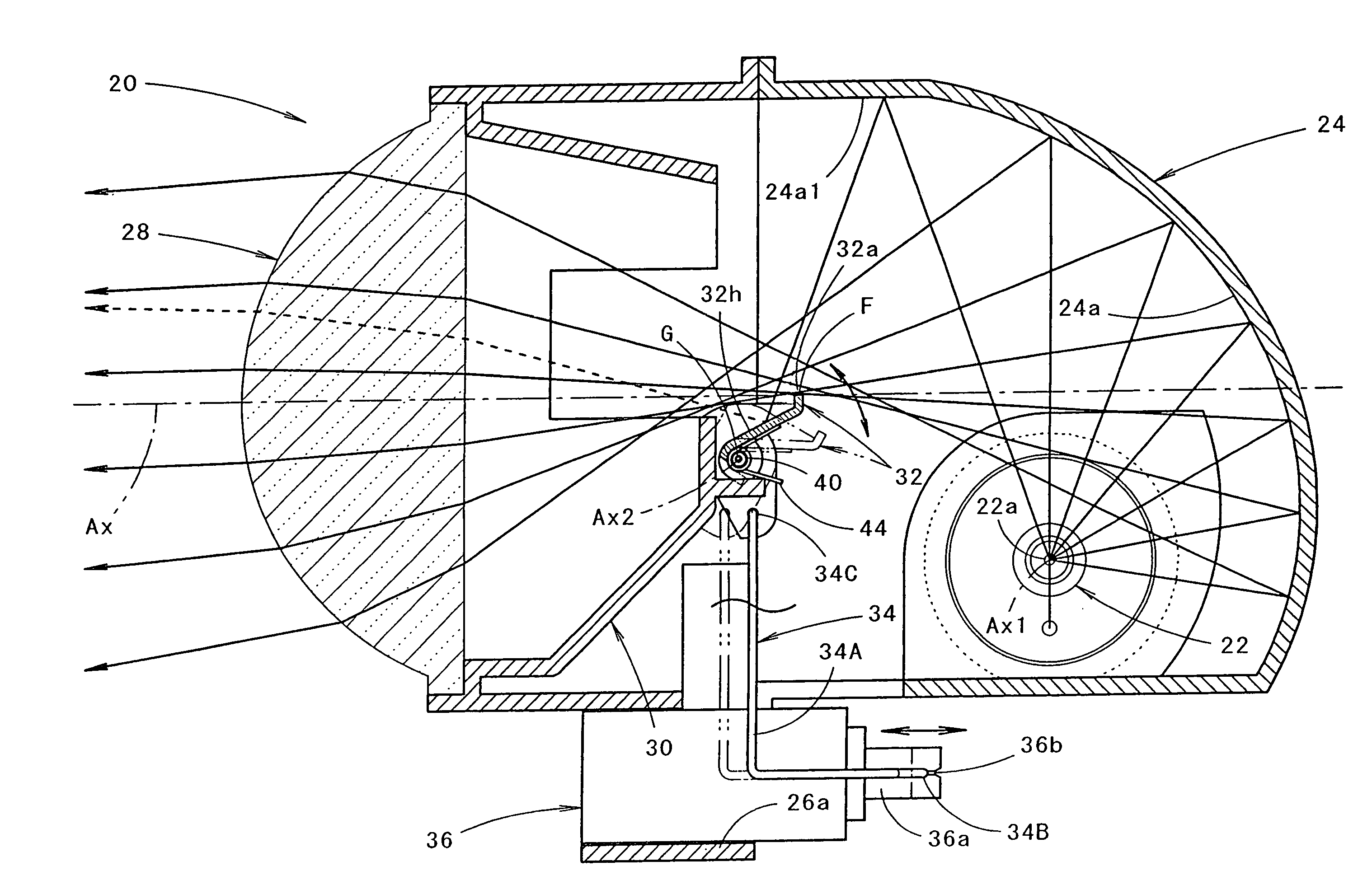
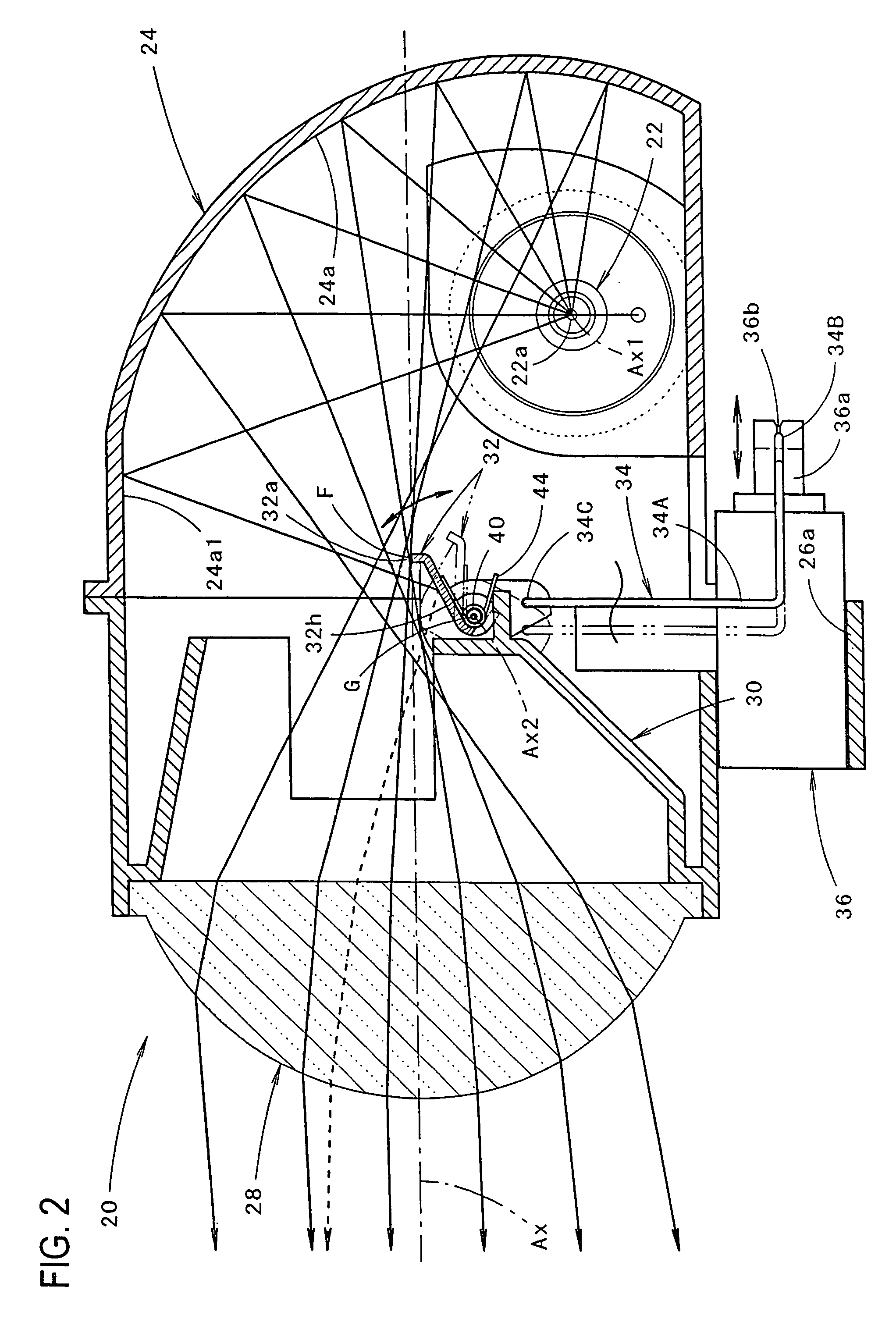
[0044]The lamp unit 20 is, as seen from FIGS. 2 and 3, a projection type lamp un...


PUM


Abstract

A vehicular headlamp including a light blocking moveable shade which is provided to rotate about a rotational axis line that extends in the width direction of a vehicle. The moveable shade is linked to an actuator via a link member and has an outwardly curved upper end edge that extends along the rear focal plane of a projection lens when the moveable shade is in the light shielding or light blocking position. The distance between the rotational axis line and a connection point of the moveable shade and the link member is set to be smaller than the distance between the rotational axis line and the upper end edge of the moveable shade, and the center of gravity of the moveable shade is positioned in the vicinity of the rotational axis line.

Description

BACKGROUND OF THE INVENTION[0001]1. Field of the Invention[0002]The present invention relates to a projector type vehicular headlamp and more particularly to a vehicular headlamp that has therein a moveable shade.[0003]2. Description of the Related Art[0004]Generally, a projector type headlamp includes a projection lens disposed on an optical axis extending in a longitudinal direction of the vehicle, a light source disposed to the rear side of a rear side focal point of the projection lens, and a reflector that reflects light from the light source toward the optical axis. When the projector type headlamp generates a low beam light distribution pattern, a shade provided so that its upper end edge is in the vicinity of the optical axis near the rear side focal point of the projection lens shields a part of the reflected light from the reflector, thus forming a predetermined cut-off line at the upper edge of the low beam light distribution pattern.[0005]Japanese Patent Application Laid...

Claims


Application Information

Patent Timeline
Patent Type & Authority Patents(United States)
IPC IPC(8): F21S8/10F21Y101/00
CPCF21S48/1778F21S48/145F21S41/43F21S41/689F21W2102/18
Inventor MOCHIZUKI, KATSUHITOASHIZAWA, KAZUHISAOTAKA, HIROSHISUGIYAMA, YUJI
Owner KOITO MFG CO LTD
Why Eureka
Try Eureka