Laser device and method for a vehicle

Active Publication Date: 2017-10-24
KYOCERA SLD LASER INC
View PDF404 Cites 22 Cited by
  • Summary
  • Abstract
  • Description
  • Claims
  • Application Information

AI Technical Summary

Benefits of technology

[0027]It is to be appreciated that examples of the present invention provides numerous advantages over conventional techniques. According to the present invention, a laser dazzling device implemented using one or more violet, blue, or green laser diodes based on GaN coupled to phosphor member has the numerous advantages over existing DPSS approaches.
[0028]Efficiency: Because the GaN diode laser is a single stage, it is inherently more efficient and therefore requires less powerful batteries, decreasing the size, weight and cost. Moreover, the efficient generation of light minimizes waste heat which needs to be managed and carried away which further reduces size, weight, and cost.
[0029]Ruggedness and elimination of alignment: The green laser light is generated within the chip, so external optical alignment is not required to maintain lasing. This dramatically reduces cost in the manufacturing process and also eliminates failure mechanisms for the use in the field.
[0030]Broad temperature operation: The GaN diode laser approach is not sensitive to minor changes in temperature. Therefore, requirements for several control are eliminated including sensors for temperature and/or light, along with active temperature controls such as heaters or thermoelectric coolers. This greatly reduces the system complexity, cost, size, and weight, and eliminates failure mechanisms.
[0031]Elimination of the dangerous of the residual 1064 nm beam: This GaN design produces only a green laser beam and does not produce a 1064 nm beam. This eliminates the blocking filter reducing cost, and eliminating the risk of emitting an extreme

Problems solved by technology

However, many of these are impractical in impromptu security environments, and such measures may not show enough force to deter potentially hostile parties.
If a serious threat is anticipated, historically, warning shots were fired, but this action can actually accelerate tensions and result in unwanted and unnecessary escalation of force if the shots are perceived incorrectly by the approaching party.
Moreover, once the warning shots have b

Method used


Image

  • Laser device and method for a vehicle
  • Laser device and method for a vehicle
  • Laser device and method for a vehicle

Examples


Embodiment Construction

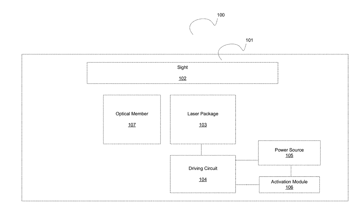
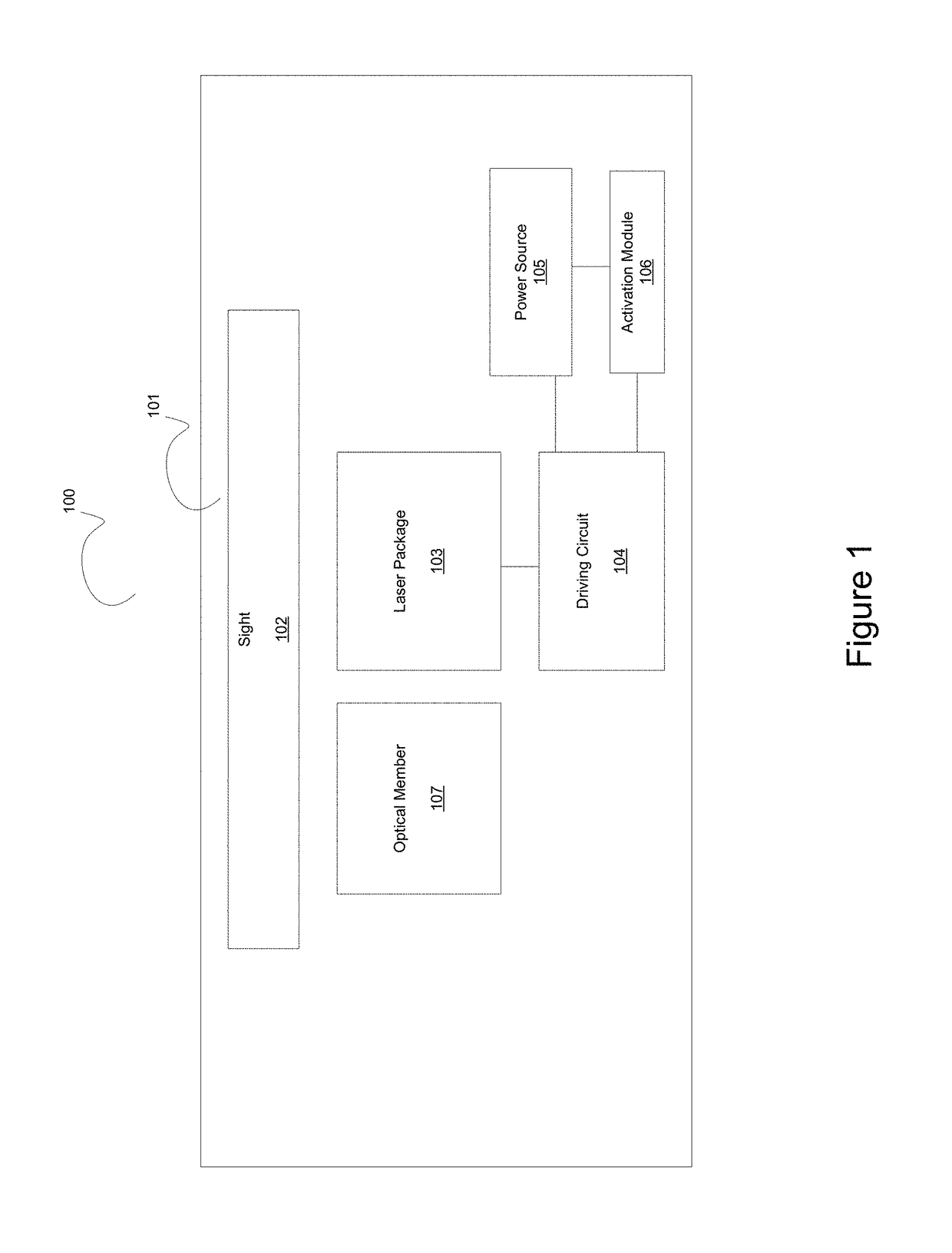
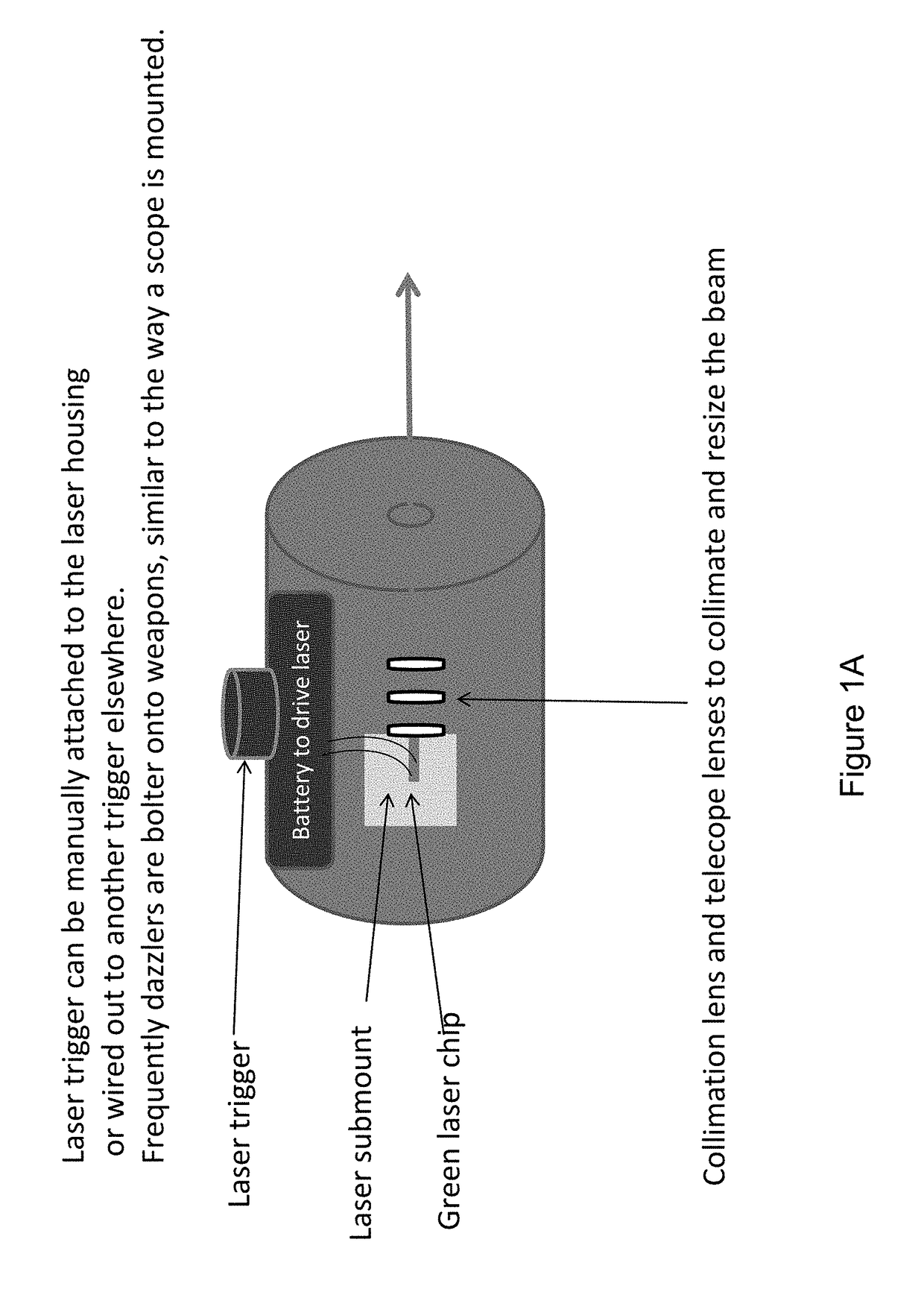
[0045]According to the present invention, laser devices are provided. More specifically, examples of the present invention provide laser dazzling devices power by one or more green laser diodes characterized by a wavelength of about 500 nm to 540 nm. In preferable examples, the laser dazzling device is configured from a laser pumped phosphor (LPP). In such LPP applications the laser diodes are characterized by violet wavelengths of about 390 nm to about 425 nm or blue wavelengths of about 425 nm to about 480 nm. The laser beam from the laser diodes excites a phosphor material, which functions to convert the incident laser beam to longer wavelength emission such as green emission, yellow emission, or red emission. One or more of the emission colors from the laser diode and phosphor members comprises the dazzling electromagnetic radiation output from the dazzling device. In various examples, laser dazzling devices include polar, non-polar, and / or semi-polar green laser diodes. In a sp...


PUM


Abstract

A laser illumination or dazzler device and method. More specifically, examples of the present invention provide laser illumination or dazzling devices power by one or more violet, blue, or green laser diodes characterized by a wavelength from about 390 nm to about 550 nm. In some examples the laser illumination or dazzling devices include a laser pumped phosphor wherein a laser beam with a first wavelength excites a phosphor member to emit electromagnetic at a second wavelength. In various examples, laser illumination or dazzling devices according to the present invention include polar, non-polar, or semi-polar laser diodes. In a specific example, a single laser illumination or dazzling device includes a plurality of violet, blue, or green laser diodes. There are other examples as well.

Description

CROSS-REFERENCE TO RELATED APPLICATION[0001]This application is a continuation-in-part of U.S. application Ser. No. 13 / 938,048, filed Jul. 9, 2013, which is a continuation-in-part of U.S. application Ser. No. 12 / 787,343, filed May 25, 2010, which claims priority to U.S. Application No. 61 / 182,104, filed May 29, 2009, each of which is incorporated herein by reference in its entirety for all purposes.BACKGROUND OF THE INVENTION[0002]The present invention is related to laser devices. More specifically, examples of the present invention provide laser dazzling devices power by one or more green laser diodes characterized by a wavelength of about 500 nm to 540 nm. In various examples, laser dazzling devices include non-polar and / or semi-polar green laser diodes. In a specific example, a single laser dazzling device includes a plurality of green laser diodes, which may couple power together. There are other examples as well.[0003]As human beings become more civilized, non-lethal techniques...

Claims


Application Information

Patent Timeline
IPC IPC(8): H01S5/042H01S3/16H01S5/022H01S5/323
CPCH01S5/0428H01S5/02208H01S5/32341H01S3/1643H01S3/1603F41H13/0056H01S5/0071H01S5/02212H01S5/026H01S5/042H01S5/22H01S5/4031H01S5/4087H01S5/320275H01S5/0087F21S2/00F21V23/02H01S5/3202H01S5/34333H01S5/4012H04N9/31H04N9/77H01S5/02325
Inventor RARING, JAMES W.RUDY, PAUL
Owner KYOCERA SLD LASER INC
Why Eureka
Try Eureka