Fiber amplifier having a non-doped inner core and at least one doped gain region

a fiber amplifier and inner core technology, applied in the field of optical fiber amplifiers, can solve the problems of limited energy conversion process of such systems, thermal energy release that heats the fiber amplifier, and elevated temperatures in the core of the fiber amplifier, so as to minimize waste heat generation, overcome inherent intensity limitations, and high stokes

Active Publication Date: 2005-11-15
THE BOEING CO
View PDF20 Cites 44 Cited by
  • Summary
  • Abstract
  • Description
  • Claims
  • Application Information

AI Technical Summary

Benefits of technology

[0012]In light of the foregoing background, the present invention provides an improved a fiber amplifier and optical fiber laser system that concurrently generate an intermediate pump energy while depleting that energy through a non-linear conversion process driven by yet another signal wavelength. By generating the intermediate pump energy while depleting that energy, the fiber amplifier and optical fiber laser system of embodiments of the present invention allow a “linear gain” optical conversion process to proceed with less regard to maintaining a low-order, wave-guided, optical mode. By depleting the energy through a non-linear conversion process of high Stokes and quantum efficiencies, the fiber amplifier and optical fiber laser system of embodiments of the present invention can minimize waste heat generated in the fiber amplifier. Such a reduction in waste heat allows the non-linear process to occur in a confined core and, as such, the fiber amplifier of embodiments of the present invention can include a single-mode fiber core. The beneficial use of stimulated non-linear optical processes also overcomes inherent intensity limitations that naturally arise when the spontaneous non-linear processes are allowed to develop and propagate along the fiber.

Problems solved by technology

Although laser systems generate coherent output power in a manner that is intrinsically efficient, a physical limit referred to as the quantum defect limit typically limits the energy conversion process of such systems.
Generally, the quantum defect limit, as well as spontaneous radiation losses, miscellaneous optical absorption losses and other non-productive processes, lead to thermal energy release that heats the fiber amplifier.
For high power laser systems, such a rise in temperature can result in elevated temperatures in the core of the fiber amplifier (typically where doped lasing media is located in fiber amplifiers having a doped core).
In turn, the elevated core temperature can degrade the efficiency of the laser system, lead to unacceptable optical distortions or, in the extreme, to failure of the fiber amplifiers or surrounding system materials and components.
In addition to elevated core temperatures, many conventional fiber amplifiers performing nonlinear processes suffer from localized energy conversion and inefficient conversion of laser power.
Through proper design, such unstable operating regions can possibly be avoided, but designing around such unstable operating regions presents an additional constraint on the system optimization and operational flexibility of the system.
Furthermore, the transient conditions on start-up of the system could pass through such regions of instability, presenting unique design issues and control problems.

Method used


Image

  • Fiber amplifier having a non-doped inner core and at least one doped gain region
  • Fiber amplifier having a non-doped inner core and at least one doped gain region
  • Fiber amplifier having a non-doped inner core and at least one doped gain region

Examples


Embodiment Construction

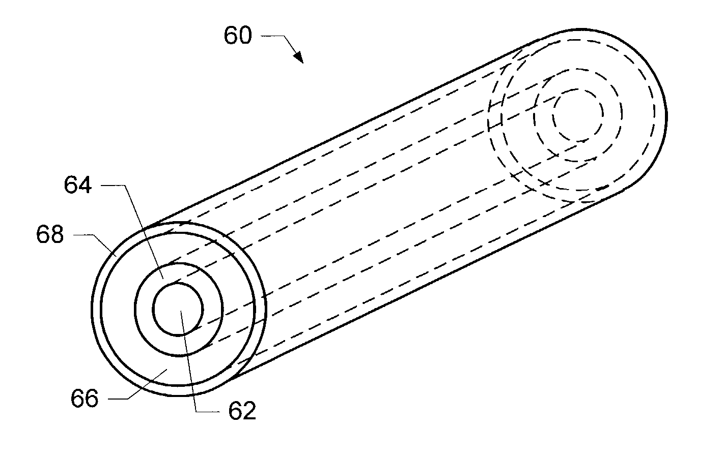
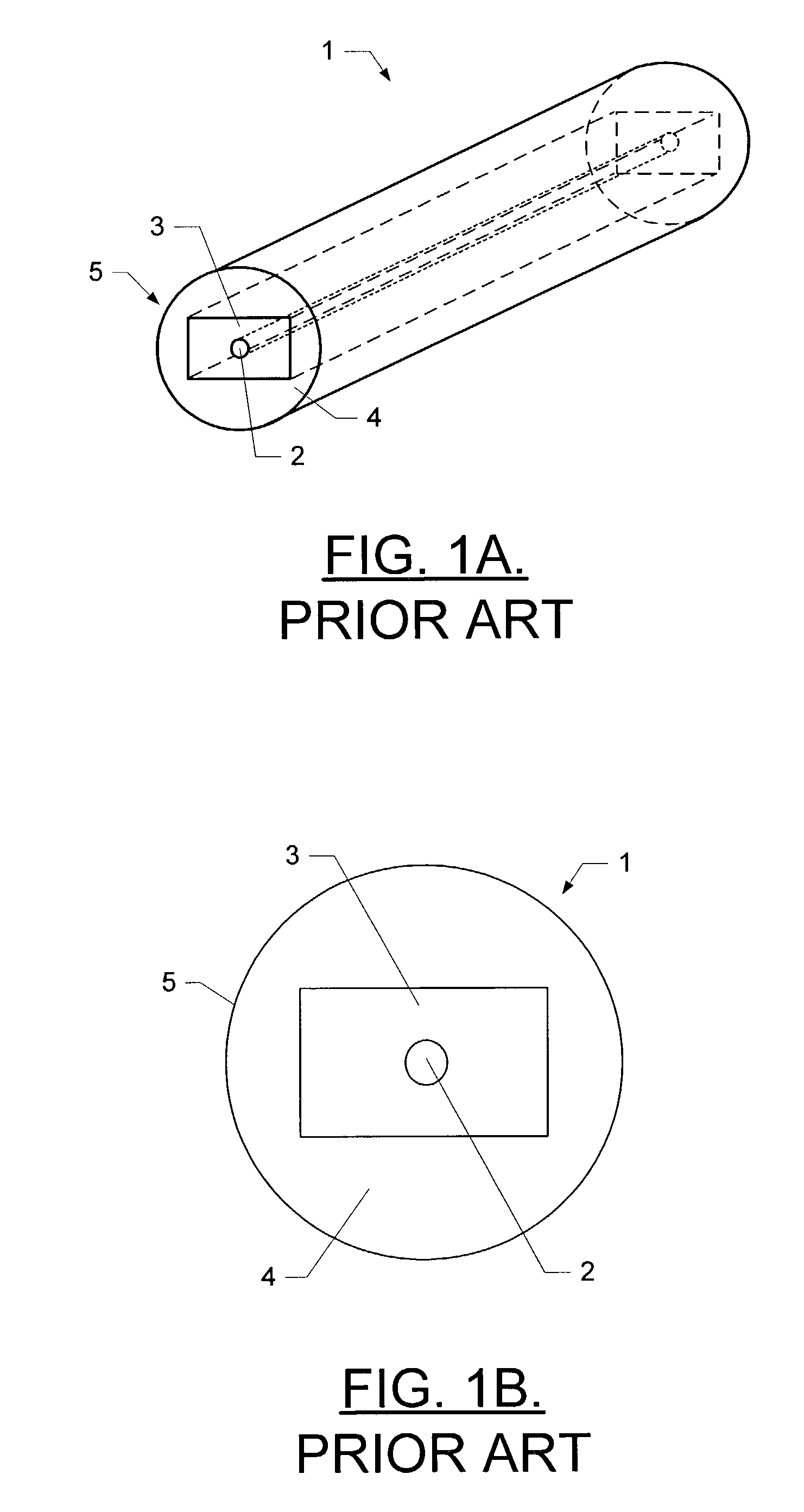
[0025]The present invention now will be described more fully hereinafter with reference to the accompanying drawings, in which preferred embodiments of the invention are shown. This invention may, however, be embodied in many different forms and should not be construed as limited to the embodiments set forth herein; rather, these embodiments are provided so that this disclosure will be thorough and complete, and will fully convey the scope of the invention to those skilled in the art. Like numbers refer to like elements throughout.

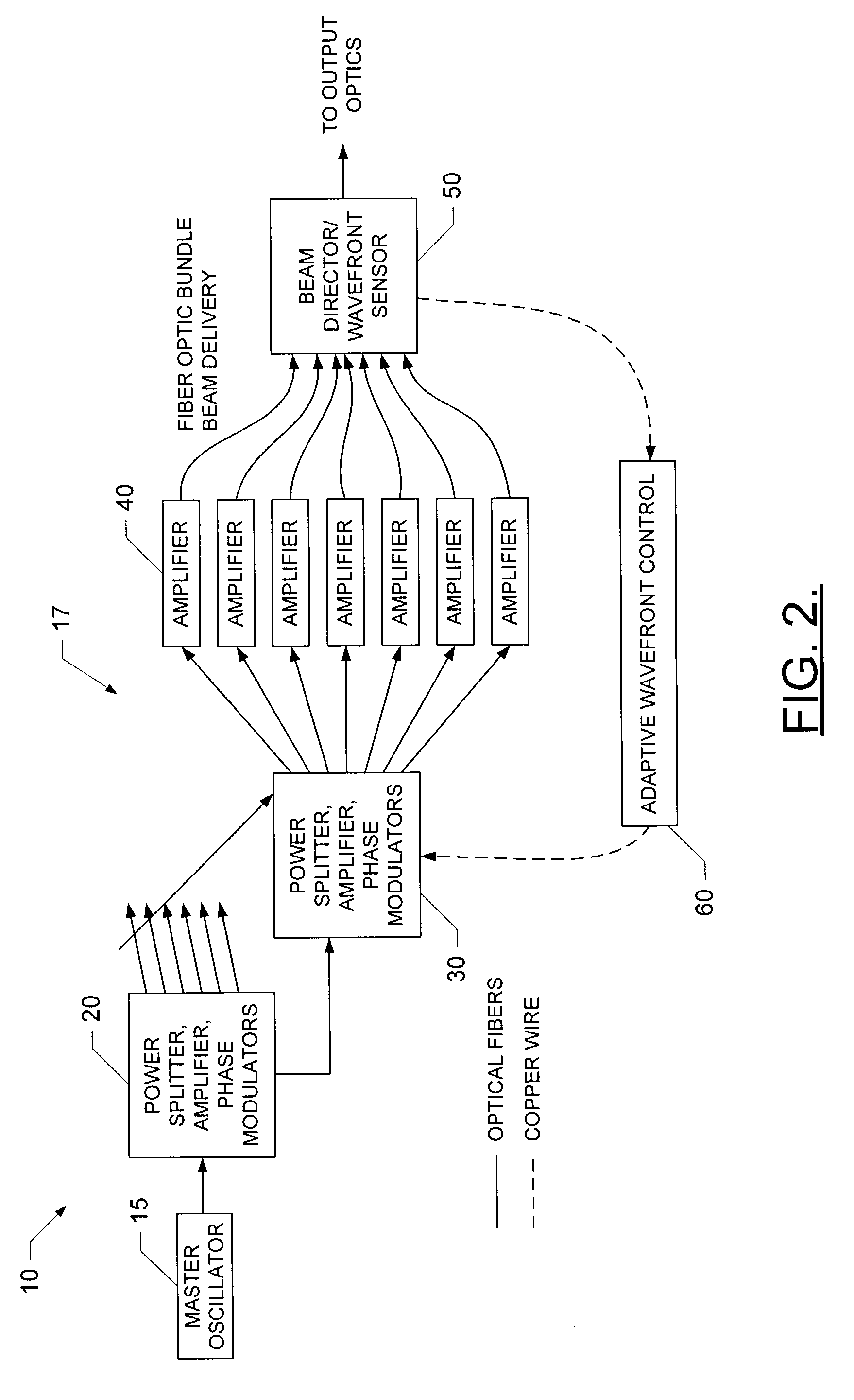
[0026]One example of a coherent phased array of fiber optic amplifiers suitable for use in the present invention for generating high-power laser beams needed for long-range radar system applications is shown in FIG. 2. This particular laser power amplifier is described in detail in U.S. Pat. No. 5,694,408, the contents of which are hereby incorporated by reference herein in its entirety. It will be appreciated that the power splitter, amplifier and phase m...


PUM


Abstract

A fiber amplifier includes at least one longitudinally extending non-doped inner core capable of transmitting signals. At least partially surrounding the inner core and extending at least partially therealong, the fiber amplifier also includes at least one gain region capable of amplifying signals propagating therethrough. The fiber amplifier also includes an outer core surrounding the gain region and the inner core and extending longitudinally therealong. The outer core is capable of transmitting pump energy such that the pump energy at least partially amplifies signals propagating through the inner core according to a nonlinear amplification process, such as a Raman or a Brillouin amplification process.

Description

FIELD OF THE INVENTION[0001]The present invention relates generally to optical fiber amplifiers and, more particularly, to techniques for coupling pump energy into the pump core layer of an optical fiber amplifier.BACKGROUND OF THE INVENTION[0002]Laser systems including fiber amplifiers are commonly used in many applications, including telecommunications applications and high power military and industrial fiber optic applications. For example, both U.S. Pat. No. 5,946,130, issued Aug. 31, 1999 to Rice and U.S. Pat. No. 5,694,408 issued Dec. 2, 1997 to Bott et al. describe many such applications in which laser systems including fiber amplifiers are employed including the processing of materials, laser weapon and laser ranging systems, and a variety of medical and other applications. In this regard, such fiber amplifiers generally include optical fibers that passively transmit optical power, fibers that experience or are designed to enhance performance of a laser through nonlinear opt...

Claims


Application Information

Patent Timeline
Patent Type & Authority Patents(United States)
IPC IPC(8): H01S3/30H01S3/06H01S3/00H01S3/067H04B10/00H01S3/094
CPCH01S3/06708H01S3/094003H01S3/302H01S3/06729
Inventor AVIZONIS, PETRAS V.DAVIS, JAMES A.WHELAN, DAVID
Owner THE BOEING CO
Why Eureka
Try Eureka