Device for concentrating optical radiation

a technology of optical radiation and concentrator, applied in the direction of optical radiation measurement, instruments for comonautical navigation, instruments, etc., can solve the problems of not providing any passive solar tracking ability, inefficient light direction, and needing a tracking mechanism, so as to minimize waste heat, minimize costs, and select bandwidth capability

Inactive Publication Date: 2001-08-14
ILLINOIS INSTITUTE OF TECHNOLOGY
View PDF22 Cites 183 Cited by
  • Summary
  • Abstract
  • Description
  • Claims
  • Application Information

AI Technical Summary

Benefits of technology

The advantages of the HPC-PV panel include the following:
3. Multiple panel embodiments, flexible in design.
4. Selective bandwidth capability to minimize waste heat, design feature.
5. Transparent HPC allows for additional films or collection devices behind the PV panel, hence minimizing costs associated with structural requirements and land requirements.

Problems solved by technology

The luminescent centers reradiate longer wavelength light in a 360 degree solid angle and so are inefficient in directing light to one edge of the plate or to a small region of the edge.
However, this solar concentrator needs to be aligned to the sun and does not provide for any passive solar tracking ability.
However, Ando et al employ a single angle of incidence and a single wavelength, and thus require a tracking mechanism and cannot utilized the entire solar spectrum.
This invention has the disadvantage of multiple reflection losses in the guiding plate and high absorption losses in some of the more cost effective embodiments.
Also this invention posses difficult optical fabrication problems and hence is more expensive to fabricate.

Method used


Image

  • Device for concentrating optical radiation
  • Device for concentrating optical radiation
  • Device for concentrating optical radiation

Examples


example 1

Devices comprising a multiplexed (angular, spectral, and spatial) holographic film bonded to a low iron glass plate have been fabricated with large angular acceptance. A gelatin holographic film was coated onto a 3 mm thick, low iron glass plate (Solarphire Glass). Holographic optical elements were recorded into the film using an argon ion laser set to a wavelength of 488 nm.

The film plate is then bonded to another 3 mm thick, low iron glass plate (Solarphire glass) utilizing EVA adhesive from Springbom Labs. EVA is a common adhesive used in photovoltaic module construction. A photovoltaic cell was then bonded to the rear surface of the glass utilizing NOA 61 optical adhesive. The back surface of the cell was then protected by bonding a thin aluminum plate to the back of the cell with a conventional 3M very high bond double sided tape. The device measured 6 inches by 9 inches. The PV cell was 1 inch wide and 4 inches long. The holographic regions extended beyond the edge of the cell...

example 2

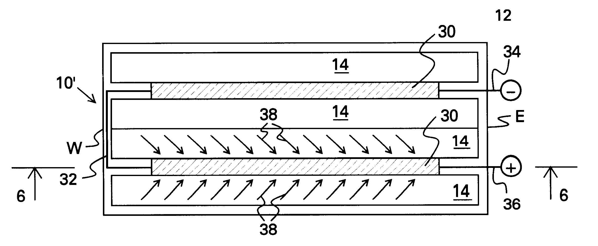
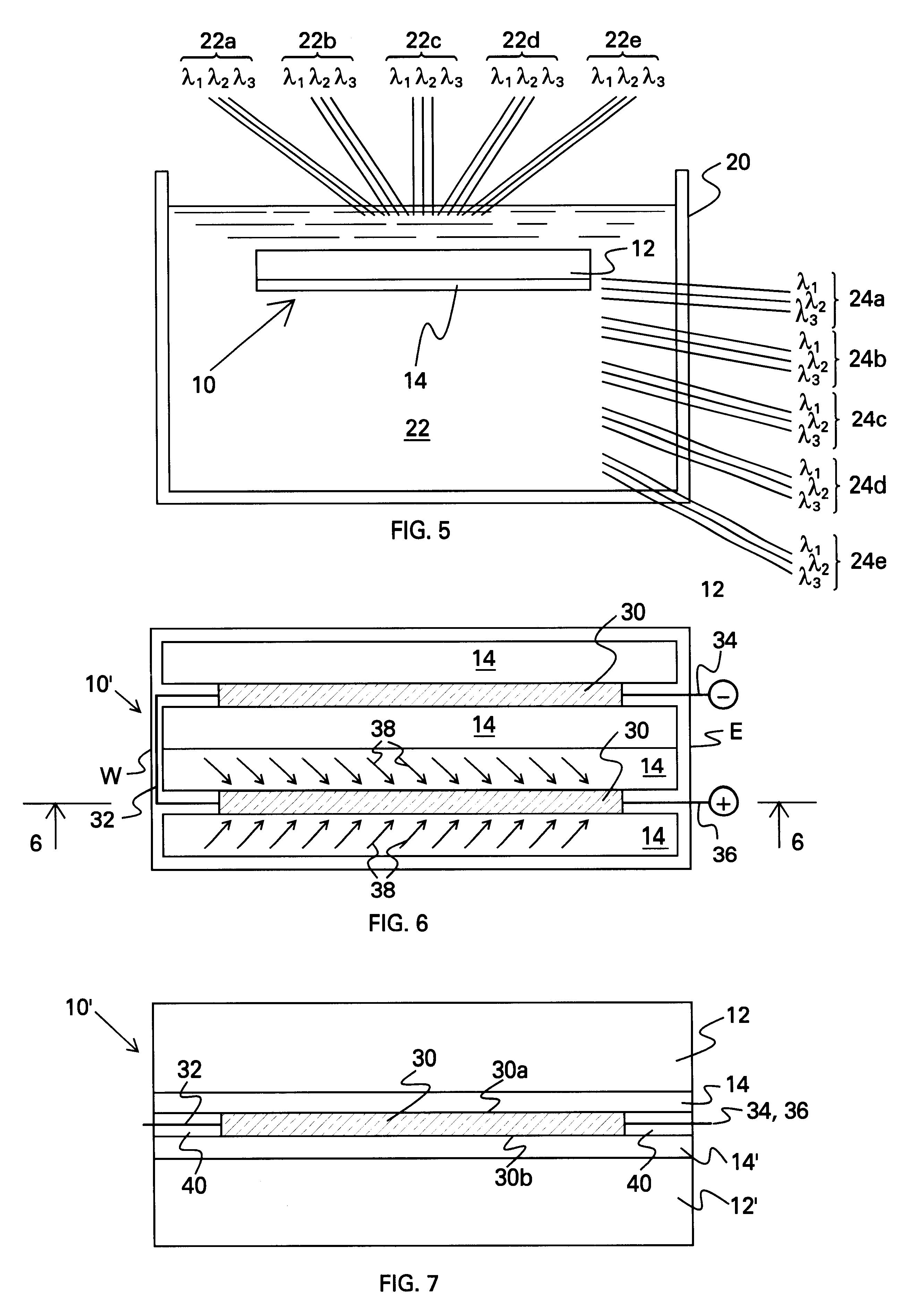
A dual holographic film layer device was constructed in the same fashion as described in Example I above with the only difference being an additional holographic film layer added to the second piece of glass. The two film layers collected energy from different parts of the solar spectrum due to the difference in the HOEs. The combined stack of two films formed an angularly and spatially multiplexed device for collection of solar energy over a broad range of input angles. The first film collected energy in the visible part of the spectrum (about 400 to 700 nm) and the second hologram collected infrared energy (about 700 to 1100 nm). Peak diffraction efficiency was 65%. Measured electric conversion efficiency for the device was 6.1%. The device collected energy from a 160 degree daily angular variation and a 45 degree seasonal variation in input angle.

While the above description contains many specific details, these should not be construed as limitations on the scope of the invention,...


PUM


Abstract

A holographic planar concentrator (HPC) for collecting and concentrating optical radiation is provided. The holographic planar concentrator comprises a planar highly transparent plate and at least one multiplexed holographic optical film mounted on a surface thereof. The multiplexed holographic optical film has recorded therein a plurality of diffractive structures having one or more regions which are angularly and spectrally multiplexed. Two or more of the regions may be configured to provide spatial multiplexing. The HPC is fabricated by: (a) recording the plurality of diffractive structures in the multiplexed holographic optical film employing angular, spectral, and, optionally, spatial multiplexing techniques; and (b) mounting the multiplexed holographic optical film on one surface of the highly transparent plate. The recording of the plurality of diffractive structures is tailored to the intended orientation of the holographic planar concentrator to solar energy. The HPC is mounted in the intended orientation for collecting solar energy and at least one solar energy-collecting device is mounted along at least one edge of the holographic planar concentrator. Examples of suitable solar energy-collecting devices include photovoltaic cells and fiber optic light guides for transmitting collected light into an interior of a building for illumination purposes and for transmitting collected solar radiation into a hot water tank for heating. The HPC permits efficient collection of solar energy without expensive requirements, while minimizing energy losses.

Description

The present invention relates to optics, particularly to the field of optical concentrators for gathering optical radiation. The optical concentrator made by the subject of the present invention may be used in all technical areas where concentrated optical radiation is utilized. It can be used for optical radiation spanning the spectrum from the ultra-violet to the infrared.Luminescent solar concentrators are known in the art and act to trap and collect light from luminescent centers dispersed in a planar sheet. Luminescent concentrators utilize the total internal reflection in the wave-guide to trap a portion of the light emitted from the luminescent centers. The luminescent centers reradiate longer wavelength light in a 360 degree solid angle and so are inefficient in directing light to one edge of the plate or to a small region of the edge.One example of a solar concentrator known in the art utilizes a hologram and a prism or plate; see, e.g., U.S. Pat. No. 4,863,224, issued to A...

Claims


Application Information

Patent Timeline
Patent Type & Authority Patents(United States)
IPC IPC(8): F24J2/06G02B5/18G03H1/26H01L31/052H01L31/0232F24S23/00H01L31/054
CPCF24J2/06G02B5/1814G03H1/26H01L31/0232H01L31/0547H01L31/0543Y02B10/20Y02E10/44Y02E10/52Y02B10/10H01L31/054F24S23/00F24S50/20Y02E10/47H01L31/055
Inventor ROSENBERG, GLENN A.
Owner ILLINOIS INSTITUTE OF TECHNOLOGY
Why Eureka
Try Eureka