Method to thaw frozen coolant in a fuel cell system

Active Publication Date: 2012-04-05
GM GLOBAL TECH OPERATIONS LLC
View PDF1 Cites 4 Cited by
  • Summary
  • Abstract
  • Description
  • Claims
  • Application Information

AI Technical Summary

Benefits of technology

[0010]In accordance with the teachings of the present invention, a method is disclosed for increasing the temperature of a cooling fluid used to control the temperature of a fuel cell stack at a system freeze start-up. The method includes determining that the cooling fluid is frozen or nearly

Problems solved by technology

MEAs are relatively expensive to manufacture and require certain conditions for effective operation.
In spite of the low temperature properties of the cooling fluid, it has been found that under certain low temperature conditions, the cooling fluid will become slushy and possibly fr

Method used


Image

  • Method to thaw frozen coolant in a fuel cell system
  • Method to thaw frozen coolant in a fuel cell system
  • Method to thaw frozen coolant in a fuel cell system

Examples


Embodiment Construction

[0014]The following discussion of the embodiments of the invention directed to a method for increasing the temperature of a cooling fluid that controls the temperature of fuel cell stack at system freeze start-up is merely exemplary in nature, and is in no way intended to limit the invention or its applications or uses.

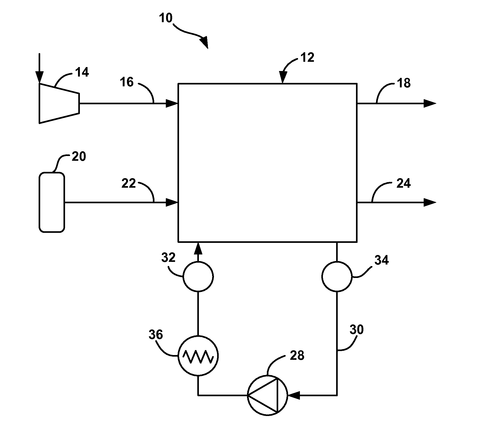
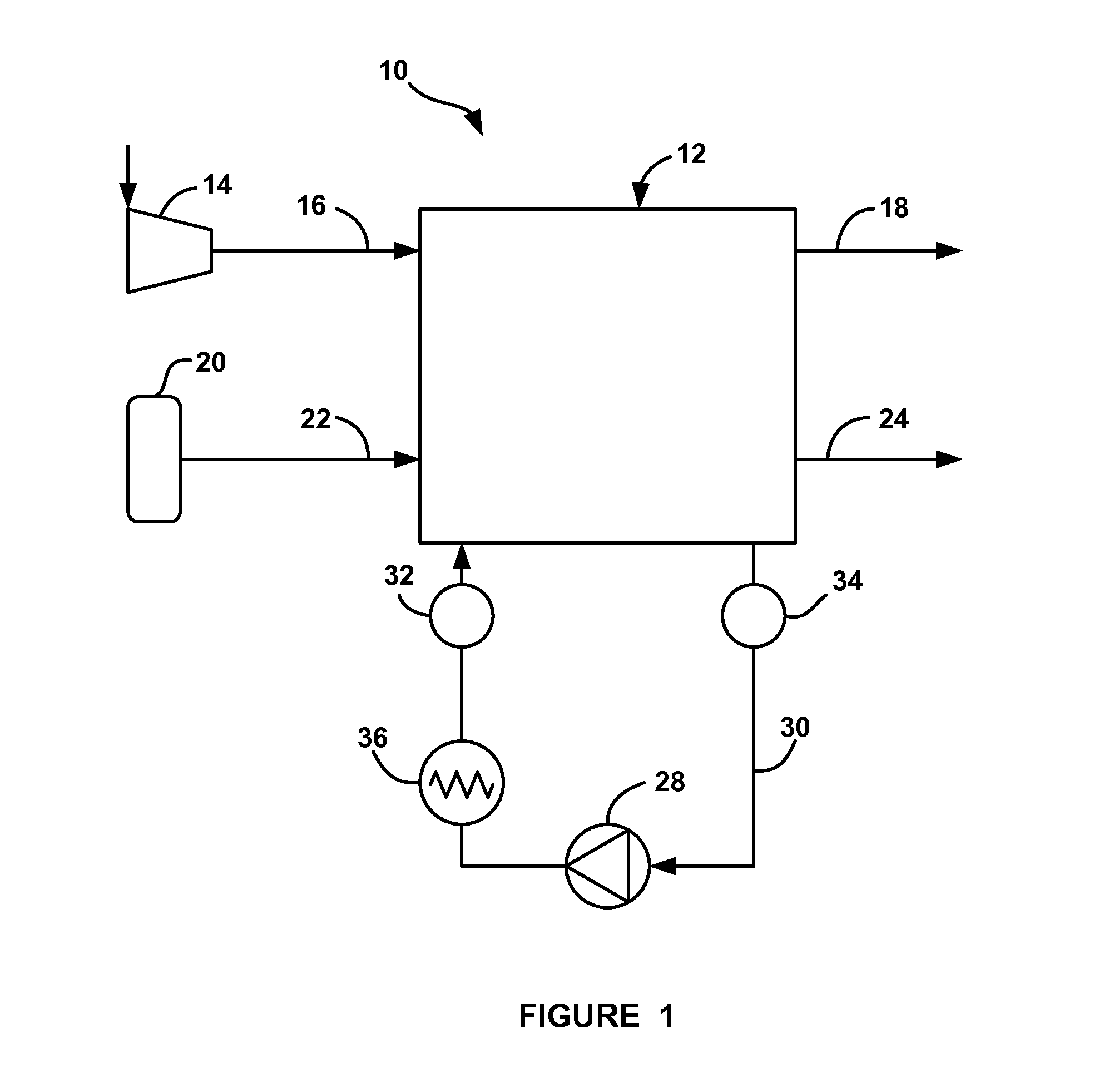
[0015]FIG. 1 is a simplified schematic plan view of a fuel cell system 10 including a fuel cell stack 12. The fuel cell stack 12 includes a cathode side that receives air from a compressor 14 on a cathode input line 16 and provides a cathode exhaust gas on a cathode exhaust gas line 18. The fuel cell stack 12 also includes an anode side that receives a hydrogen gas from a hydrogen source 20, such as a high pressure tank, on an anode input line 22 and provides an anode exhaust gas on an anode exhaust gas line 24. The system 10 further includes a thermal sub-system that provides a cooling fluid flow to the fuel cell stack 12. The thermal sub-system includes a high tempe...


PUM


Abstract

A method for increasing the temperature of a cooling fluid used to control the temperature of a fuel cell stack at a system freeze start-up. The method includes determining that the cooling fluid is frozen or nearly frozen, and if so, deactivating excessive power draw on the fuel cell stack to minimize stack waste heat and activating a cooling fluid heater to heat the cooling fluid. Once it is determined that the cooling fluid is not frozen or is flowing, then the method initiates a normal system start-up.

Description

BACKGROUND OF THE INVENTION[0001]1. Field of the Invention[0002]This invention relates generally to a method for increasing the temperature of a cooling fluid flowing through a fuel cell stack in a fuel cell system and, more particularly, to a method for increasing the temperature of a frozen or nearly frozen cooling fluid that cools a fuel cell stack at a system freeze start-up that includes limiting stack waste heat by preventing excessive power draw from the stack and heating the cooling fluid flowing through a coolant loop external to the fuel cell stack.[0003]2. Discussion of the Related Art[0004]Hydrogen is a very attractive fuel because it is clean and can be used to efficiently produce electricity in a fuel cell. A hydrogen fuel cell is an electro-chemical device that includes an anode and a cathode with an electrolyte therebetween. The anode receives hydrogen gas and the cathode receives oxygen or air. The hydrogen gas is dissociated in the anode to generate free protons an...

Claims


Application Information

Patent Timeline
IPC IPC(8): H01M8/04
CPCH01M8/04Y02E60/50H01M8/04925H01M8/0494H01M8/04723H01M16/006H01M8/04358H01M8/04365H01M8/04955Y02E60/10
Inventor RAINVILLE, JOSEPH D.GERZSENY, JOSEPH C.ROGAHN, AARONKIRKLIN, MATTHEW C.
Owner GM GLOBAL TECH OPERATIONS LLC
Why Eureka
Try Eureka