
Method and Apparatus for Controlling Bottomhole Temperature in Deviated Wells

Inactive Publication Date: 2011-03-03
BAKER HUGHES INC
View PDF59 Cites 15 Cited by
  • Summary
  • Abstract
  • Description
  • Claims
  • Application Information

AI Technical Summary

Benefits of technology

[0007]Another embodiment of the disclosure provides apparatus for conducting a drilling operation in a borehole. In one embodiment, the apparatus may include: a drill string including a bottomhole assembly (BHA) carrying a drill bit at an end thereof; a surface source configured to supply a fluid under pressure through the drillstring and the drill bit into an annulus between

Problems solved by technology

This can result in increased compressive hoop stress in the borehole wall due to thermal expansion.
The increased stress on the borehole wall can lead to failure of the borehole wall.

Method used


Image

  • Method and Apparatus for Controlling Bottomhole Temperature in Deviated Wells
  • Method and Apparatus for Controlling Bottomhole Temperature in Deviated Wells
  • Method and Apparatus for Controlling Bottomhole Temperature in Deviated Wells

Examples


Embodiment Construction

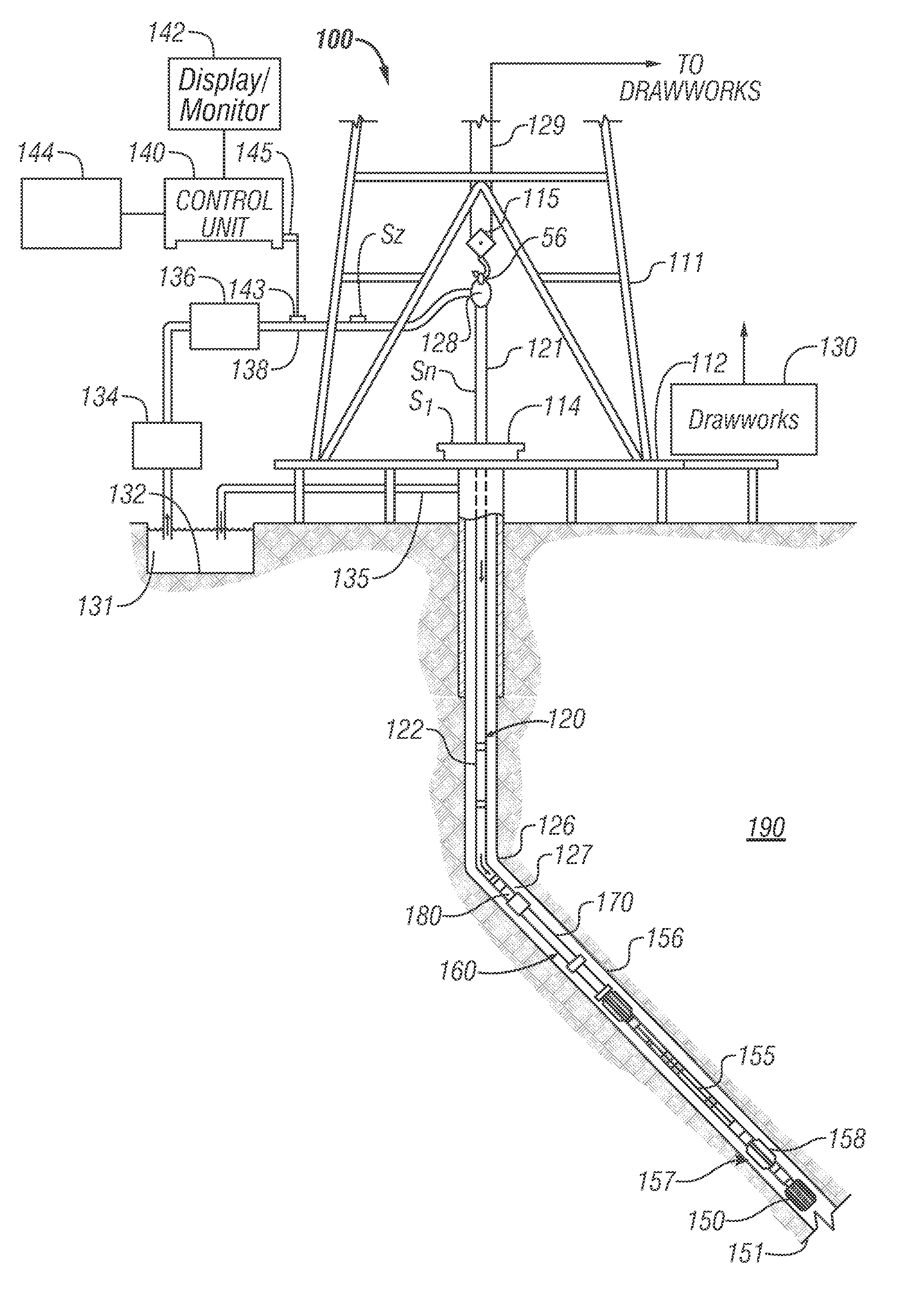
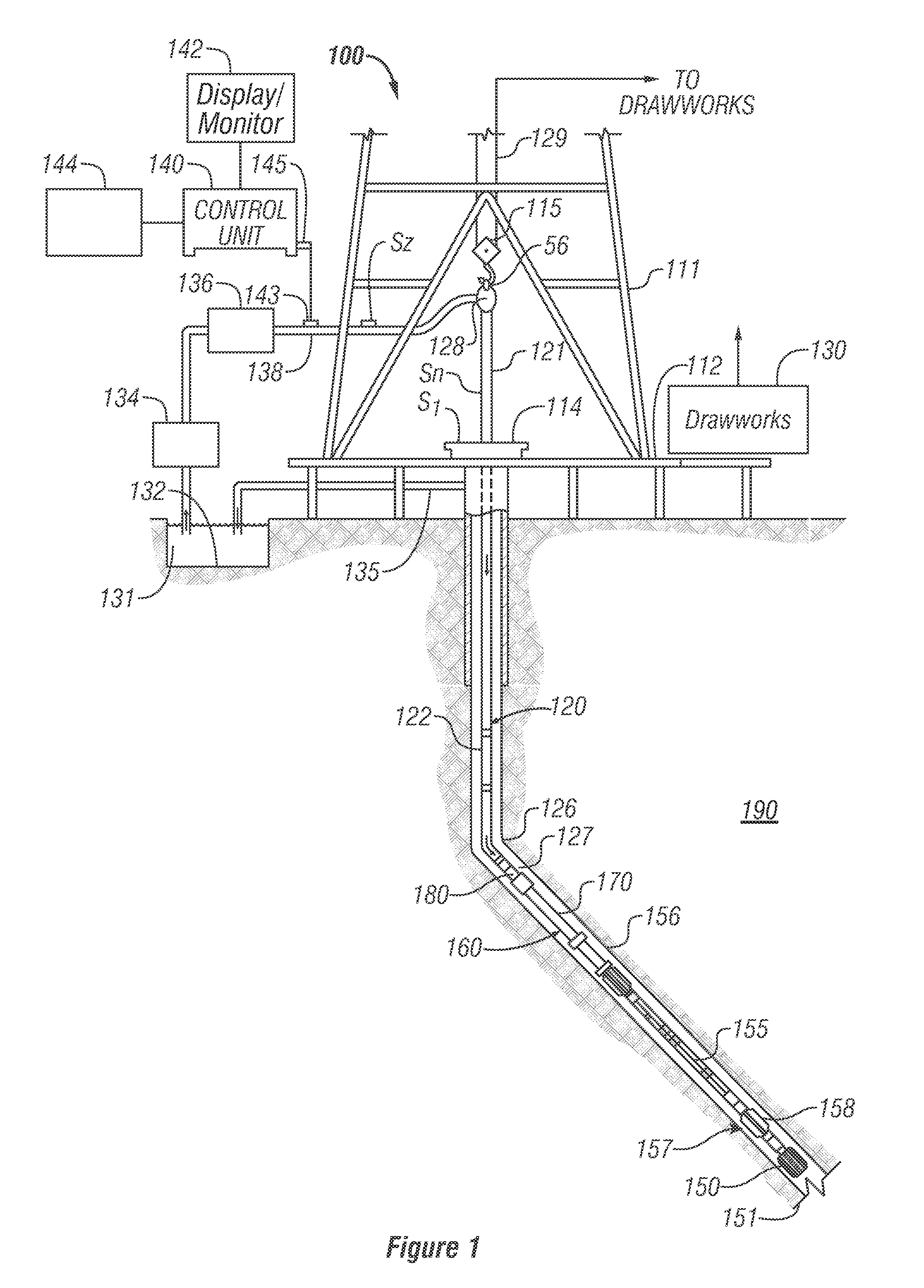
[0025]FIG. 1 shows a schematic diagram of a drilling system 100 configured to drill a borehole 126 according to one embodiment of the disclosure. System 100 is shown to include a conventional derrick 111 erected on a derrick floor 112 that supports a rotary table 114 rotated by a prime mover (not shown) at a desired rotational speed to rotate a drill string 120. Alternatively, the drill string 120 may be rotated by a top drive (not shown). The drill string 120 includes a jointed drilling tubulars or pipe 122, BHA 160 and a drill bit 150 at the downhole end of the BHA 160 extends downward from the rotary table 114 into the borehole 126. The drill bit 150 disintegrates the geological formations when rotated. The drill string 120 is coupled to a drawworks 130 via a kelly joint 121, swivel 128 and line 129 through a system of pulleys 115. During drilling operations, the drawworks 130 is operated to control the weight on bit and the rate of penetration of the drill string 120 into the bo...


PUM


Abstract

An apparatus and method for reducing temperature along a bottomhole assembly during a drilling operation is provided. In one aspect the bottomhole temperature may be reduced by drilling a borehole using a drill string having a bottomhole assembly at an end thereof, circulating a fluid through the drill string and an annulus between the drill string and the borehole, diverting a selected portion of the fluid from the drill string into the annulus at a selected location above the drill bit to reduce pressure drop across at least a portion of the bottomhole assembly to reduce temperature of the bottomhole assembly during the drilling operation.

Description

CROSS-REFERENCE TO RELATED APPLICATIONS[0001]This application claims priority to provisional patent application Ser. No. 61 / 236,802, filed Aug. 25, 2009.BACKGROUND OF THE DISCLOSURE 1. Field of the Disclosure[0002]This disclosure relates generally to drilling of lateral wellbores for recovery of hydrocarbons, and more particularly to maintaining temperature of a bottomhole assembly below certain threshold temperature. 2. Description of the Related Art[0003]To obtain hydrocarbons such as oil and gas, boreholes are drilled by rotating a drill bit attached at a drill string end. The drill string may include a jointed rotatable pipe or a coiled tube. Boreholes may be vertical, deviated or horizontal. A drilling fluid (also referred to as “mud) is pumped from the surface into the drill string, which fluid discharges at the drill bit bottom and circulates to the surface through the annulus between the drill string and the borehole. Modern directional drilling systems generally employ a bo...

Claims


Application Information

Patent Timeline
IPC IPC(8): E21B21/08E21B7/00
CPCE21B21/103E21B23/006E21B47/065E21B44/00E21B36/001E21B47/07
Inventor FINCHER, ROGER W.WATKINS, LARRY A.TRICHEL, DONALD K.OESTERBERG, MARCUS
Owner BAKER HUGHES INC
Learn More