Connector

a technology of connecting rods and connecting rods, applied in the direction of incorrect coupling prevention, coupling device connection, electrical equipment, etc., can solve the problems of deformation of the connecting rod, inability to secure the moving rod, and inability to move inadvertently

Inactive Publication Date: 2007-09-11
SUMITOMO WIRING SYST LTD
View PDF7 Cites 24 Cited by
  • Summary
  • Abstract
  • Description
  • Claims
  • Application Information

AI Technical Summary

Benefits of technology

[0008]The invention relates to a connector assembly that includes a male connector and a female connector. The male connector has a male housing with opposite front and front and rear ends. Male terminal fittings are accommodated in the male housing and have tabs that project towards the front end. A forwardly open hood projects forward on the male housing and surrounds the tabs of male terminal fittings. The female connector has a female housing that can be fit in the hood of the male housing. Flexibly deformable locking pieces are accommodated in the hood and project forward towards the open front end. A locking projection is formed at the front end of each locking piece. A plate-shaped moving plate is accommodated in the hood and extends substantially orthogonal to a mating direction of the female and male connectors. The moving plate includes positioning holes for receiving the tabs and locking holes for receiving the locking pieces. A thick reinforcement is formed along the periphery of each locking hole of the moving plate to fill a gap between the moving plate and each of the locking projections. The locking projection of each locking piece is locked to the periphery of the respective locking hole to prevent a movement of the moving plate. However, this locked state is released, when the female connector is fit in the male connector. Thus, the moving plate can be moved rearward and the tabs project from the respective positioning holes. The thick reinforcement along the periphery of each locking hole of the moving plate fills the gap between the moving plate and the projection and prevents the moving plate from being unlocked inadvertently from the locking state.
[0009]The locking projection preferably includes front and rear projections. The front projection is forward of the moving plate and the rear projection is rearward of the moving plate when the moving plate is locked to the locking projection. A rear surface of the front projection is sloped and becomes distant from a front surface of the moving plate as the rear surface of the front projection approaches a projected end thereof. The reinforcement is formed on the front surface of the moving plate and confronts the slope of the front projection and a front surface of the rear projection so that the moving plate is sandwiched between the front and rear projections. Thus, the moving plate is locked firmly locked between the front projection forward of the moving plate and the rear projection rearward of the moving plate. Further the reinforcement between the locking projection and the moving plate prevents the moving plate from being unlocked inadvertently from the locking piece.
[0010]The moving plate preferably does not contact an inner surface of the hood. Thus, there is no friction between the moving plate and the inner surface of the hood during movement of the moving plate and a force required to move the moving plate is reduced.

Problems solved by technology

The gap reduces the engaged surface areas between the locking projection and the mating lock, and hence the moving plate is not held securely.
As a result, there is a fear that the deformed moving plate could become unlocked from the locking projection and could move inadvertently.

Method used


Image

  • Connector
  • Connector
  • Connector

Examples


Embodiment Construction

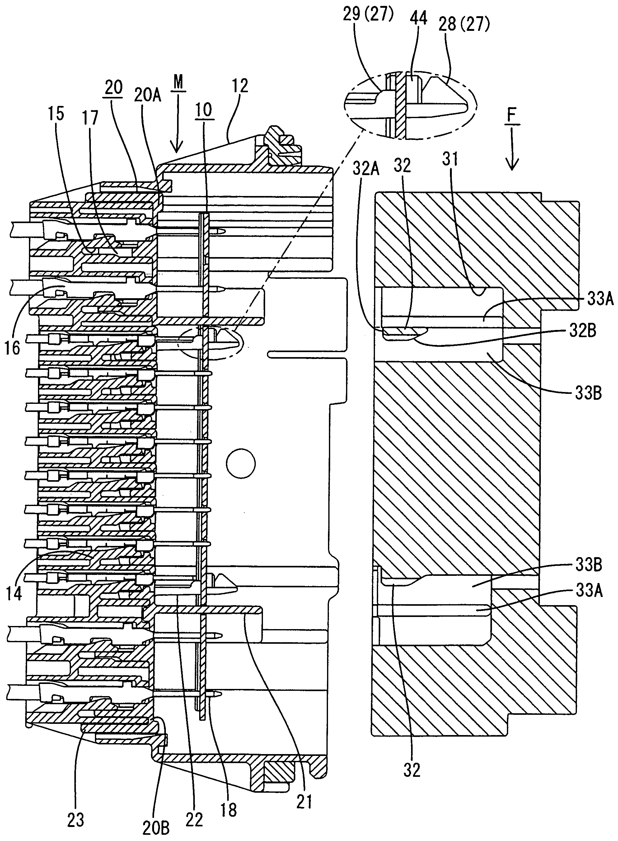
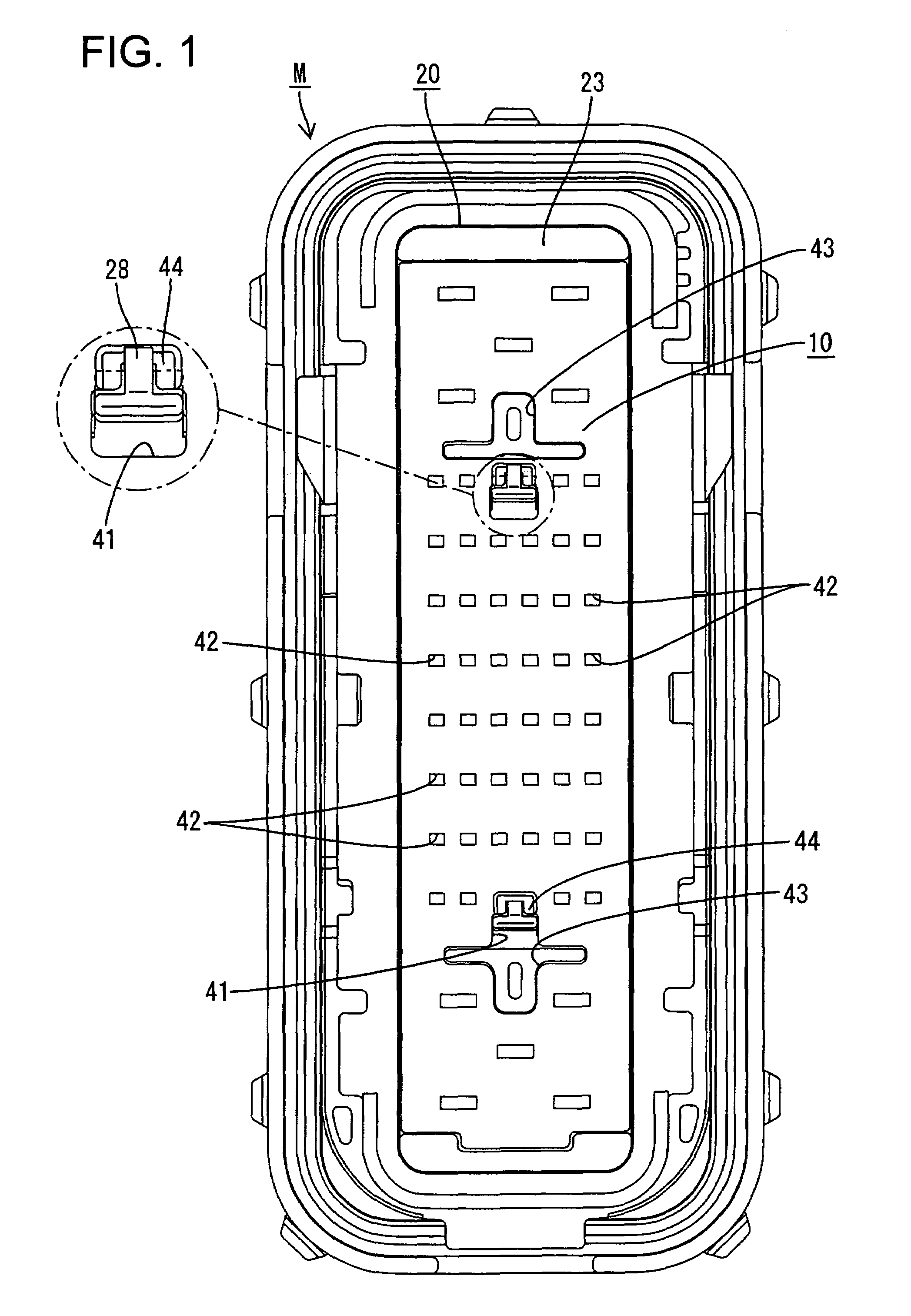
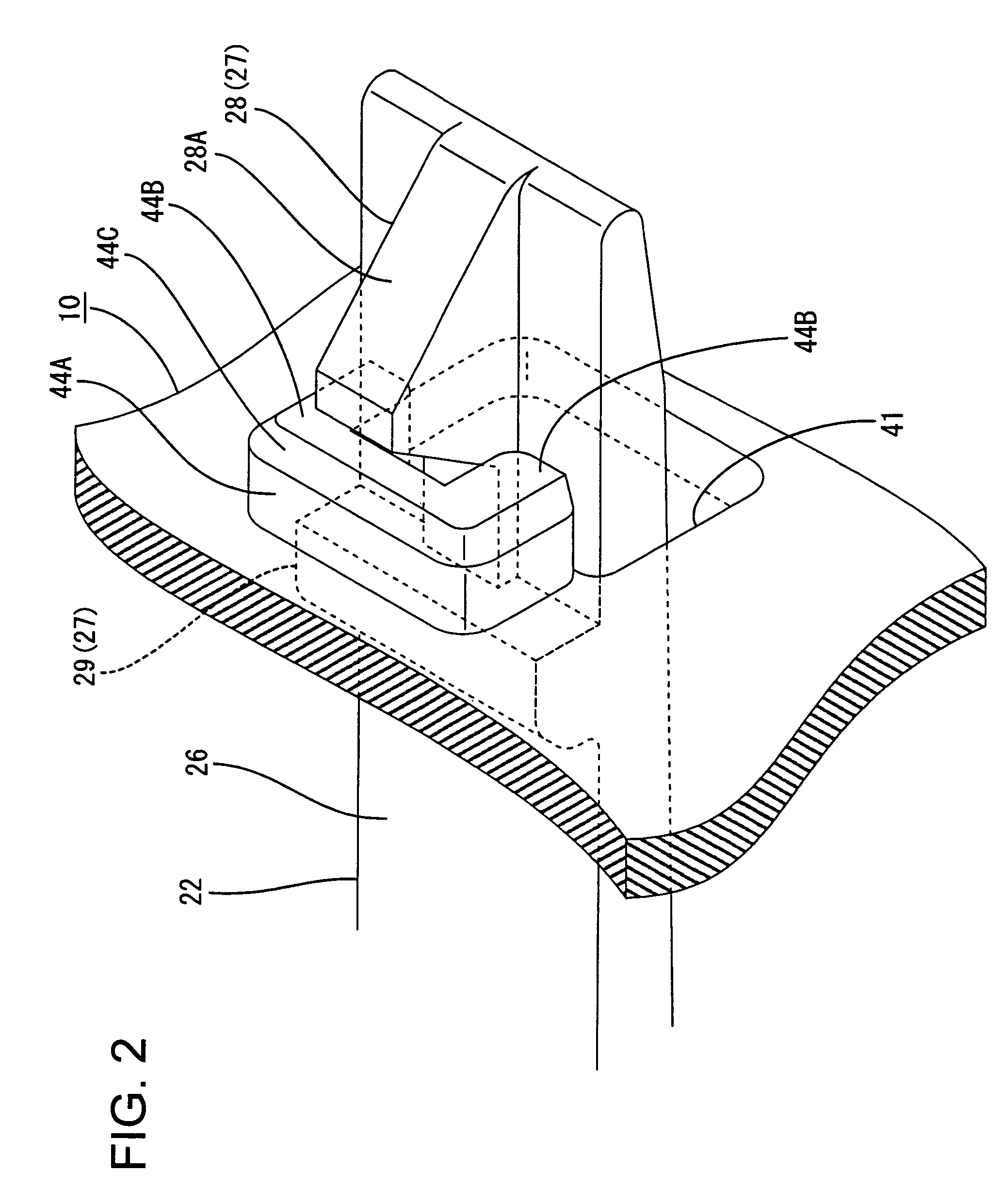
[0020]A connector assembly in accordance with the invention is illustrated in FIGS. 1 through 8, and includes a female connector F that can be fit in a male connector M. The male connector M has a moving plate 10 and a retainer 20. In the description made below, the fit-in ends of the female connector F and the male connector M are referred to as the front.

[0021]The female connector F has a female housing for accommodating a plurality of female terminal fittings (not shown) therein. As shown in FIG. 6, the female housing is made of a synthetic resin and is long in a height direction, which is the direction in which female terminal fittings are arranged. Upper and lower concave portions 31 are formed at the top and bottom of the female connector F and open at the front end of the female connector F. The upper and lower concave portions 31 extend in a longitudinal direction of the female connector F and have a depth dimension set to receive a portion of the retainer 20 of the male con...


PUM


Abstract

A retainer (20) and a moving plate (10) are inserted into a hood (12) of a connector (F). A locking piece (22) projects from a front surface of the retainer (20). A locking hole (41) is formed through the moving plate (10). The locking piece (22) penetrates through the locking hole (41) to lock a locking projection (27) at a front end of the locking piece (22) to a periphery of the locking hole (41). Thus, the moving plate (10) is supported and is prevented from moving longitudinally. A thick reinforcement (44) is formed on the periphery of the locking hole (41) of the moving plate (10) to fill a gap between the moving plate (10) and the locking projection (27).

Description

BACKGROUND OF THE INVENTION[0001]1. Field of the Invention[0002]The invention relates to a connector that has a moving plate.[0003]2. Description of the Related Art[0004]Published U.S. Pat. Appl. Publication No. US 2002 / 0168895 A1 discloses a connector with a hood that has a closed rear end and an open front end. The connector also has a moving plate formed with a plurality of guide holes. The moving plate is accommodated movably in the hood and is connected with a guide by two cantilevered booms. The moving plate is thinned to reduce weight.[0005]Flexible locking pieces are provided for holding the moving plate in the hood. Each locking piece has a locking projection for engaging a mating lock. The locking projections rotate through circular arcs as the locking pieces deform elastically. Thus, a gap is formed between the locking surface of the locking projection and the opposed surface of the mating lock due to the locus of rotation of the locking projection. The gap reduces the en...

Claims


Application Information

Patent Timeline
Patent Type & Authority Patents(United States)
IPC IPC(8): H01R13/44
CPCH01R13/516H01R13/4538
Inventor KATSUMA, TAKATOSHI
Owner SUMITOMO WIRING SYST LTD
Why Eureka
Try Eureka