
Electrophotographic photoreceptor, and image forming method, image forming apparatus and process cartridge therefor using the electrophotographic photoreceptor

a photoreceptor and electrophotography technology, applied in the direction of electrographic process apparatus, instruments, corona discharge, etc., can solve the problems of poor cleaning, increased cost, and inability to properly perform the image forming process, and achieve the effect of stably producing quality images and low surface friction coefficien

Active Publication Date: 2007-09-11
RICOH KK
View PDF55 Cites 48 Cited by
  • Summary
  • Abstract
  • Description
  • Claims
  • Application Information

AI Technical Summary

Benefits of technology

[0018]Accordingly, an object of the present invention is to provide a low-cost and heavy-duty electrophotographic photoreceptor maintaining a low surface friction coefficient, and stably producing quality images, and remaining cleaned for long periods of time.

Problems solved by technology

When a certain amount of the photosensitive layer is abraded, electric properties of the photoreceptors change and the image forming process cannot properly be performed.
However, the spheric toner dives under a contact part between the cleaning blade and photoreceptor and scrapes therethrough, resulting in poor cleaning.
However, an image forming apparatus equipped with such a mechanism around the photoreceptor inevitably becomes large and complicated, resulting in cost increase and complicated maintenance.
However, when the surface layer or protective layer of a photoreceptor includes comparatively a small amount of a particulate fluorocarbon resin, a surface friction coefficient of the photoreceptor gradually increases as images are repeatedly produced, although being low at the beginning.
However, the particulate fluorocarbon resin tends to agglutinate in a resin solution and is difficult to disperse therein.
However, any surface layers formed by these methods include comparatively a small amount of a particulate fluorocarbon resin, and insufficiently maintain their low friction coefficients for long periods.
Even in the method disclosed in Japanese Laid-Open Patent Publication No. 6-130711, wherein a large amount of the particulate fluorocarbon resin is included in the surface layer, it is considered that the particulate fluorocarbon resin is difficult to finely disperse because of tending to agglutinate, although a particle diameter thereof after dispersed is not disclosed.
When the concavities and convexities of the surface layer become large, it is considered that poor cleaning or irregular toner images occurs.
When the particulate fluorocarbon resin is eccentrically-located in the surface layer, the surface layer microscopically has a part having a high friction coefficient and a part having a low friction coefficient, and therefore it is considered that poor cleaning occurs as well.
Further, when the secondary agglomerated particles of the particulate fluorocarbon resin are too large, a laser beam is scattered thereon, which causes an irregular latent image, and a shortage of light amount and a shortage of potential contrast, resulting in production of abnormal images.
As mentioned above, although a trial of reducing a surface friction coefficient of a photoreceptor to prevent production of abnormal images by using a particulate fluorocarbon resin is made, continuousness of a low surface friction coefficient, dispersibility of the particulate fluorocarbon resin, and downsizing of an image forming apparatus are not yet satisfactory.

Method used


Image

  • Electrophotographic photoreceptor, and image forming method, image forming apparatus and process cartridge therefor using the electrophotographic photoreceptor
  • Electrophotographic photoreceptor, and image forming method, image forming apparatus and process cartridge therefor using the electrophotographic photoreceptor
  • Electrophotographic photoreceptor, and image forming method, image forming apparatus and process cartridge therefor using the electrophotographic photoreceptor

Examples


example 1

[0168]The following materials were mixed and dispersed in a ball mill for 12 hrs to prepare an undercoat layer coating liquid:

[0169]

Alkyd resin (Bekkolite M6401-50 from15Dainippon Ink & Chemicals, Inc.)Melamine resin (Super Bekkamin G-821-60 from10Dainippon Ink & Chemicals, Inc.)Methyl ethyl ketone150Titanium oxide powder (Tipaque CR-El from90Ishihara Sangyo Kaisha, Ltd.)

[0170]The thus prepared undercoat layer coating liquid was coated on a cylindrical aluminium substrate having a diameter of 90 mm and a length of 392 mm by a dip coating method, and the coated liquid was dried at 130° C. for 20 min to form an undercoat layer having a thickness of 3.5 μm on the substrate.

[0171]Next, the following materials were mixed and dispersed in a ball mill for 48 hrs to prepare a mixture:

[0172]

Polyvinylbutyral resin 4(XYHL from Union Carbide Corp.)Cyclohexanone150Bisazo pigment having the following 10Formula (1):(1)

[0173]Further, 210 parts of cyclohexanone were included in the mixture and the m...

example 2

[0196]The procedures of preparation and evaluation of the electrophotographic photoreceptor in Example 1 were repeated to prepare and evaluate an electrophotographic photoreceptor of Example 2 except for including 55 parts of the PFA dispersion in the resin liquid formed of 16 parts of Bisphenol Z-type polycarbonate resin dissolved in the mixed solvent of 420 parts of tetrahydrofuran and 120 of cyclohexanone to prepare a coating liquid; and insonifying the coating liquid for 10 min to prepare a protective layer coating liquid.

example 3

[0197]The procedures of preparation and evaluation of the electrophotographic photoreceptor in Example 1 were repeated to prepare and evaluate an electrophotographic photoreceptor of Example 3 except for including 300 parts of the PFA dispersion in the resin liquid formed of 16 parts of Bisphenol Z-type polycarbonate resin dissolved in the mixed solvent of 420 parts of tetrahydrofuran and 120 of cyclohexanone to prepare a coating liquid; and insonifying the coating liquid for 10 min to prepare a protective layer coating liquid.


PUM


Abstract

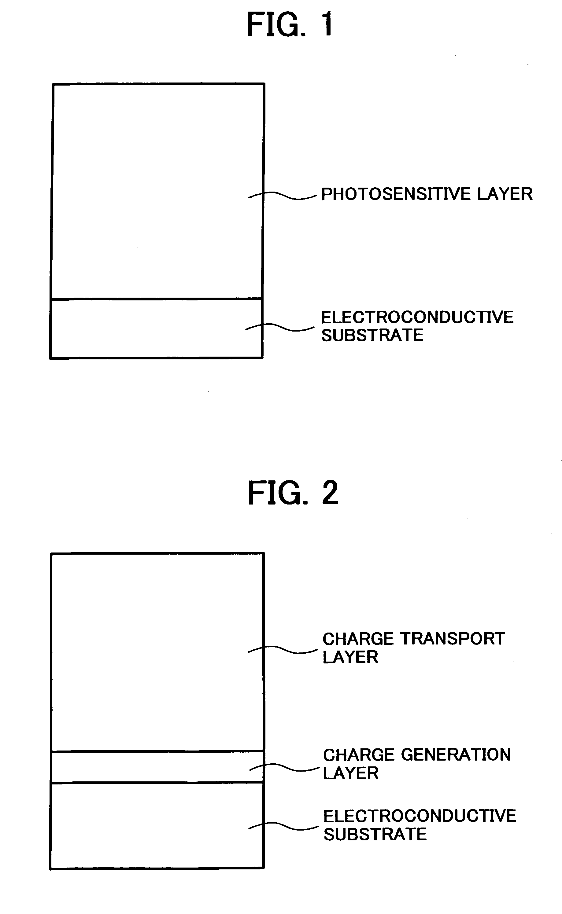
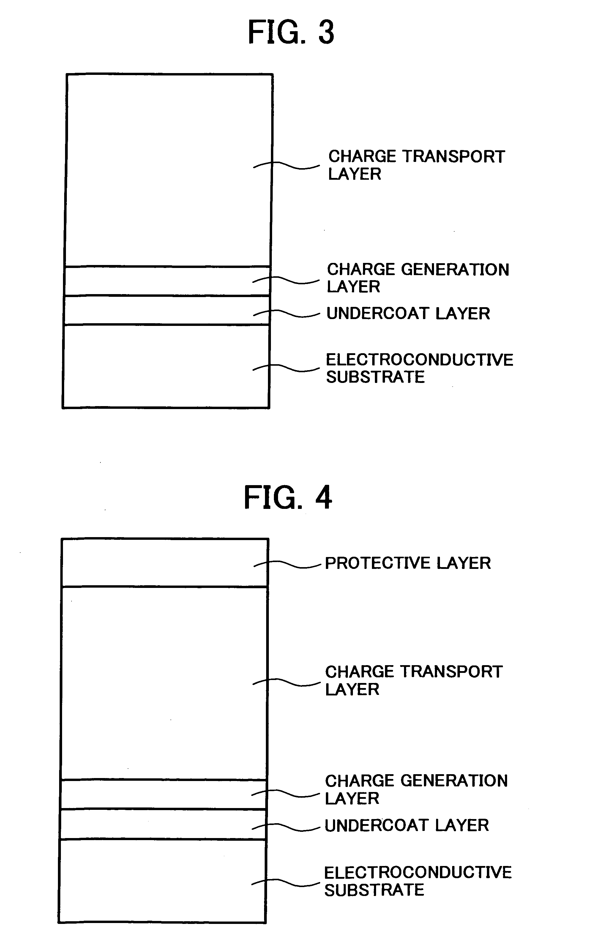
An electrophotographic photoreceptor including an electroconductive substrate and a photosensitive layer located overlying the electroconductive substrate, wherein an outermost layer of the electrophotographic photoreceptor includes a particulate fluorine-containing resin, and wherein a primary particle of the particulate fluorine-containing resin and a secondary particle formed of agglomerated primary particles thereof, which are projected from a surface of the outermost layer and have an average particle diameter of from 0.15 to 3 μm, are present in an area ratio not less than 10% based on total surface area of the outermost layer.

Description

BACKGROUND OF THE INVENTION[0001]1. Field of the Invention[0002]The present invention relates to an electrophotographic photoreceptor for use in copiers, electrostatic printings, printers, electrostatic recordings, etc.; and to an image forming apparatus, an image forming method, and a process cartridge for the image forming apparatus using the electrophotographic photoreceptor.[0003]2. Discussion of the Background[0004]In an image forming apparatus such as a copier, a printer, and a facsimile using an electrophotographic method, writing light modulated with image data is irradiated to a uniformly charged photoreceptor to form an electrostatic latent image thereon; and an image developer provides a toner to the electrostatic latent image to form a toner image thereon. Next, the image forming apparatus transfers the toner image onto a transfer sheet (recording paper) with a transferer, fixes the toner image on the transfer sheet upon application of heat and pressure with a fixer, and...

Claims


Application Information

Patent Timeline
Patent Type & Authority Patents(United States)
IPC IPC(8): G03G5/147G03G5/05
CPCG03G5/0539G03G5/14726
Inventor SUGINO, AKIHIRONOUSHO, SHINJIIKEGAMI, TAKAAKIKURIMOTO, EIJINAKAMORI, HIDEOKAMI, HIDETOSHIYAMASHITA, YASUYUKI
Owner RICOH KK
Learn More