

Image forming method, image forming apparatus and process cartridge
a technology process cartridge, which is applied in the direction of electrographic process, electrographic process apparatus, instruments, etc., can solve the problems of image deletion, difficult to reduce the cost of image forming apparatus, image bearer ablation, etc., and achieve the effect of stably producing quality images
- Summary
- Abstract
- Description
- Claims
- Application Information
AI Technical Summary
Benefits of technology
Problems solved by technology
Method used
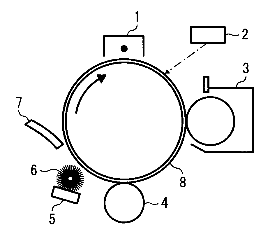
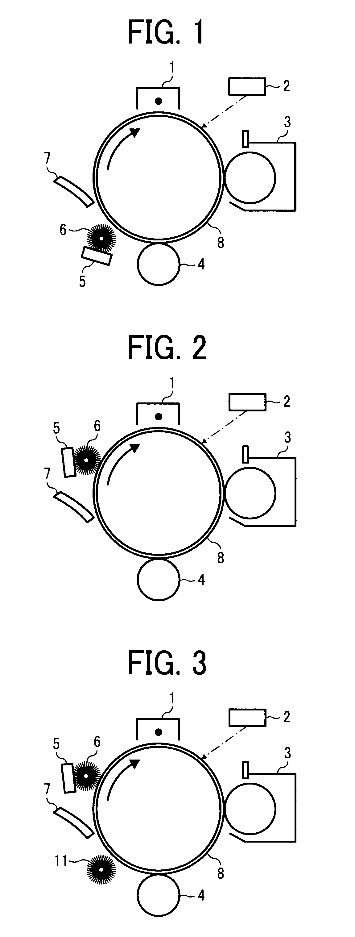
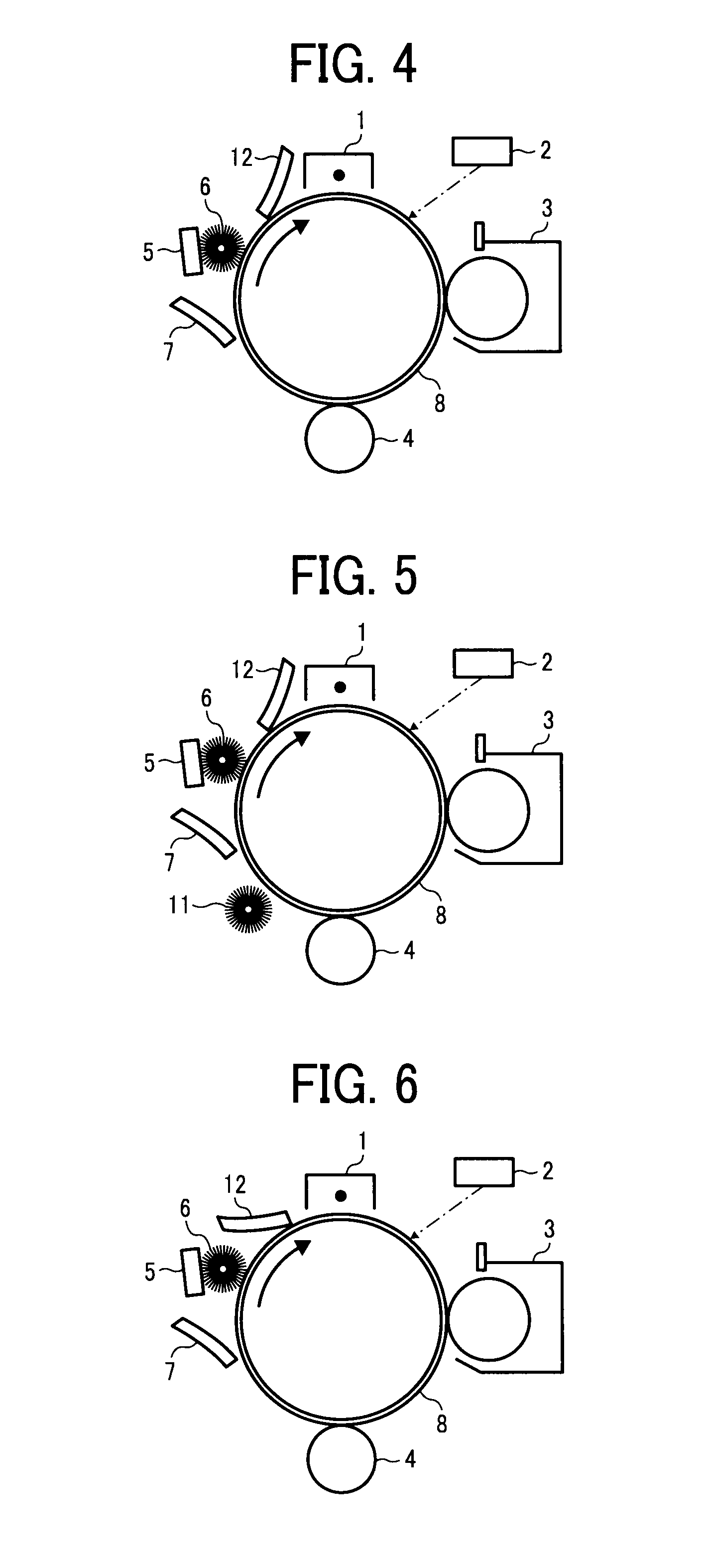
Image

Examples
example 1
(Synthesis of Unmodified Polyester Resin)
[0240]229 parts of an adduct of bisphenol A with 2 moles of ethyleneoxide, 529 parts of an adduct of bisphenol A with 3 moles of propyleneoxide, 208 parts terephthalic acid, 46 parts of adipic acid and 2 parts of dibutyltinoxide were polycondensated in a reactor vessel including a cooling pipe, a stirrer and a nitrogen inlet pipe for 8 hrs at a normal pressure and 230° C. Further, after the mixture was depressurized by 10 to 15 mm Hg and reacted for 5 hrs, 44 parts of trimellitic acid anhydride were added thereto and the mixture was reacted for 2 hrs at a normal pressure and 180° C. to prepare an unmodified polyester resin.
[0241]The unmodified polyester resin had a number-average molecular weight of 2,500, a weight-average molecular weight of 6,700, a Tg of 430° C. and an acid value of 25 mg KOH / g.
(Preparation of Masterbatch)
[0242]1,200 parts of water, 540 parts of carbon black Printex 35 from Degussa A.G. having a DBP oil absorption of 42 ml...
example 2
[0258]The procedures for preparation of the toner in Example 1 were repeated to prepare a toner except for changing 3 parts of the modified and layered inorganic mineral (Clayton APA) into 0.1 parts thereof. The properties of the toner are shown in Table 1.
example 3
[0259]The procedures for preparation of the toner in Example 1 were repeated to prepare a toner except for changing Clayton APA into layered inorganic mineral montmorillonite, at least a part of which is modified with an ammonium salt having a polyoxyethylene group, Clayton HY from Southern Clay Products, Inc. The properties of the toner are shown in Table 1.
PUM
| Property | Measurement | Unit |
|---|---|---|
| volume-average particle diameter | aaaaa | aaaaa |
| volume-average particle diameter | aaaaa | aaaaa |
| BET specific surface area | aaaaa | aaaaa |
Abstract
Description
Claims
Application Information