Shielded cable-grounding structure

a shielding layer and shielding cable technology, applied in the direction of cable termination, connection contact material, cable connection, etc., can solve the problems of large load applied to braided wire and a core portion to damage, low efficiency of operation, and fear of shielding layer damage, so as to achieve the effect of enhancing efficiency of operation, not reducing shielding capacity, and maintaining quality of connected portions

Inactive Publication Date: 2007-09-11
YAZAKI CORP
View PDF3 Cites 9 Cited by
  • Summary
  • Abstract
  • Description
  • Claims
  • Application Information

AI Technical Summary

Benefits of technology

[0010]This invention has been made in view of the above circumstances, and an object of the invention is to provide a shielded cable-grounding structure in which the efficiency of a grounding can be enhanced, and besides a noise-intercepting performance can be enhanced.
[0012]In the shielded cable-grounding structure of the above Paragraph 1), the sleeve electrically connects the wire to the flange portion of the braided wire (extended radially outwardly of the core covering portion) at the outer periphery of the insulating sheath, and therefore does not apply a large load to the braided wire and the core portion, and therefore will not damage or cut them, so that the quality can be maintained. And besides, the flange portion of the braided wire, extended radially outwardly of the core covering portion, is formed into a flange-like shape, and therefore a shielding capacity is not reduced, so that a positive grounding circuit can be formed. Furthermore, the braided wire is electrically connected to the wire without requiring an additional operation such as trimming, and therefore the efficiency of the operation can be enhanced. Therefore, the efficiency of the grounding can be enhanced, and also a noise-intercepting performance can be enhanced.
[0014]In the shielded cable-grounding structure of the above Paragraph 2), the first sleeve member is electrically connected at the outer periphery of the insulating sheath to an inner peripheral surface of the flange portion of the braided wire (extended radially outwardly of the core covering portion) with a large area of contact therebetween obtained, while the second sleeve member is electrically connected to an outer peripheral surface of the flange portion, with a large area of contact therebetween obtained. Therefore, the shielding capacity is not reduced, so that the positive grounding circuit for the wire can be formed.
[0016]In the shielded cable-grounding structure of the above Paragraph 3), the first sleeve member is electrically connected at the outer periphery of the insulating sheath to an inner peripheral surface of the flange portion of the braided wire (extended radially outwardly of the core covering portion) with a large area of contact therebetween obtained, while the second sleeve member is electrically connected to an outer peripheral surface of the flange portion, with a large area of contact therebetween obtained. Therefore, a shielding capacity is not reduced, so that the positive grounding circuit for the wire can be formed. And besides, a large load is not applied to the braided wire and the core portion, and therefore the quality of the connected portion can be maintained. Furthermore, the braided wire is electrically connected to the wire without requiring an additional operation such as trimming, and therefore the efficiency of the operation can be enhanced. Therefore, the efficiency of the grounding can be enhanced, and also the noise-intercepting performance can be enhanced.
[0017]In the shielded cable-grounding structure of the present invention, a large load is not applied to the braided wire and the core portion, and the efficiency of the grounding is enhanced, and also the noise-intercepting performance is enhanced, thereby achieving an advantage that the shielded cable of high quality can be obtained.
[0018]The flange portion may be formed by folding back a middle part of the braided wire. By such a structure, the braided wire can cover the core portion and the core covering portion on a distal end side of the shield cable with respect to the flange portion. As a result, a disturbance-intercepting capacity is secured, so that the shielding effect to the conductor is assuredly obtained.

Problems solved by technology

Therefore, there is a fear that a large load is applied to the braided wire and a core portion to damage them.
In the above JP-A-10-270123, the claws of the barrel are brought into biting engagement with the shielding layer, and therefore there is a fear that the shielding layer is damaged.
Therefore, the efficiency of the operation is low, and besides since the exposed braided wire 52 is twisted to assume a generally linear configuration, a disturbance-intercepting capacity is reduced, so that there is a fear that the effect of shielding the exposed conductor 53 is lowered.
Furthermore, much time and labor have been required for the additional operations (including the operation for trimming the distal end) for the braided wire 52.

Method used


Image

  • Shielded cable-grounding structure
  • Shielded cable-grounding structure
  • Shielded cable-grounding structure

Examples


first embodiment

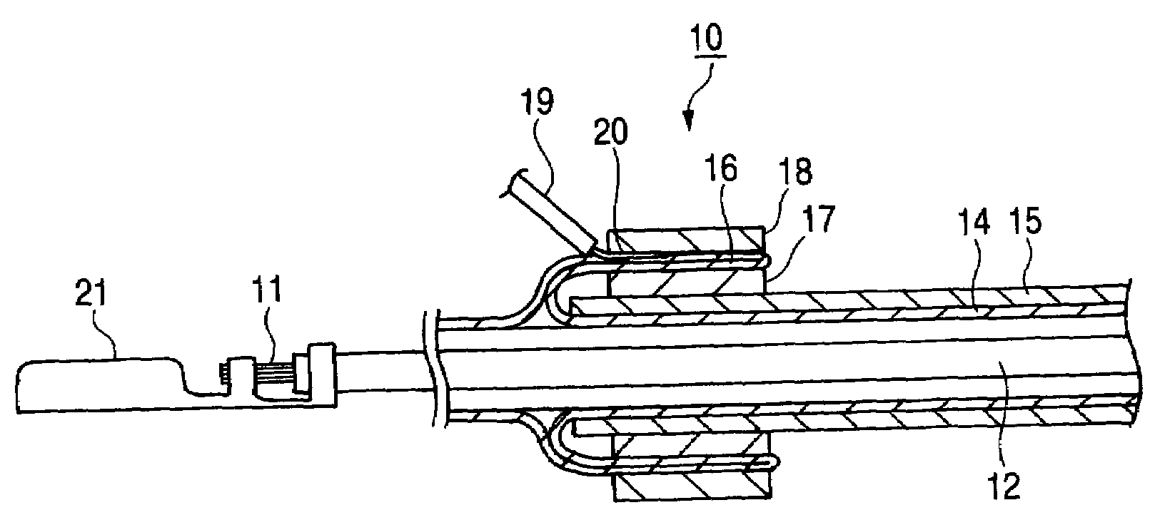
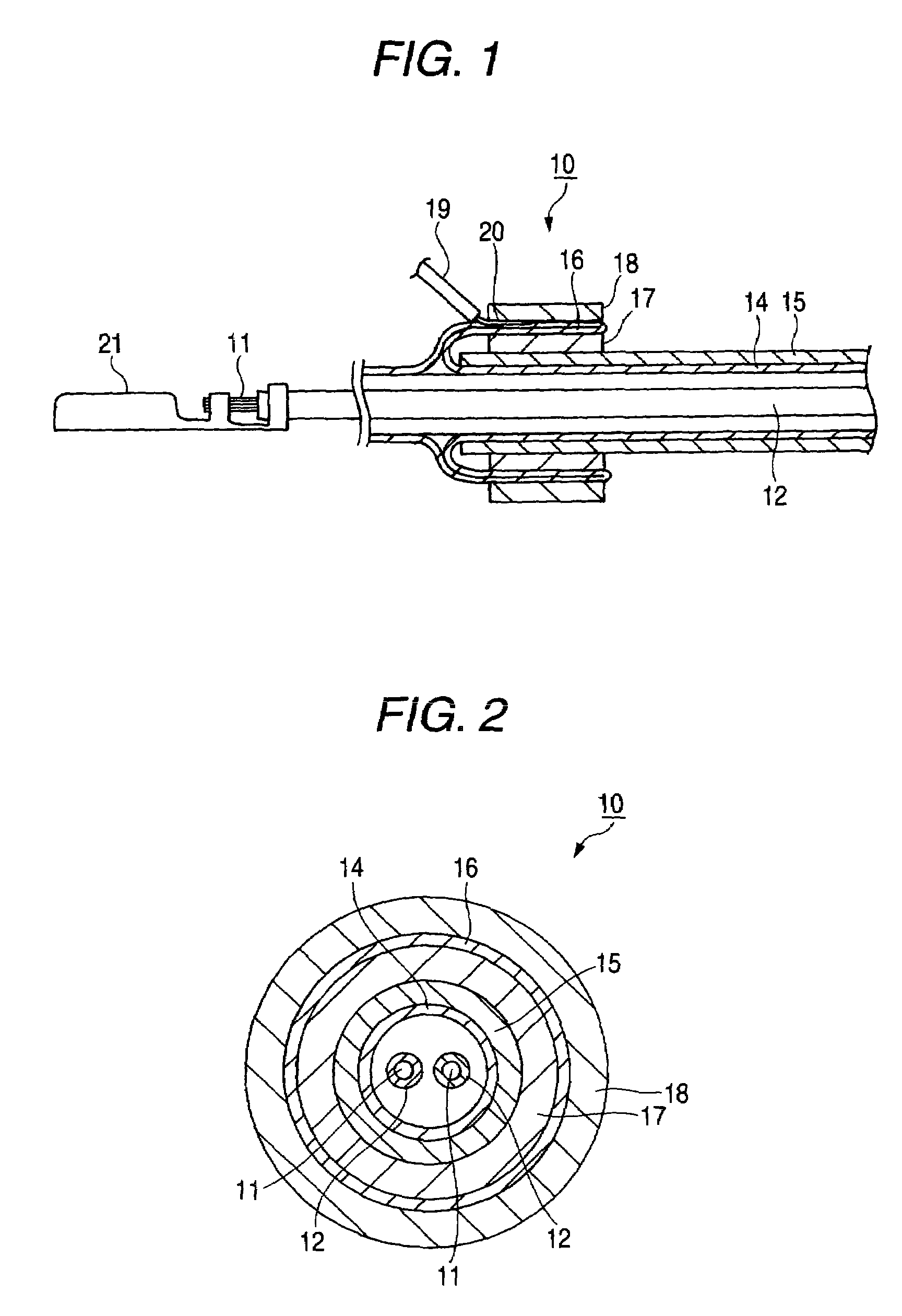
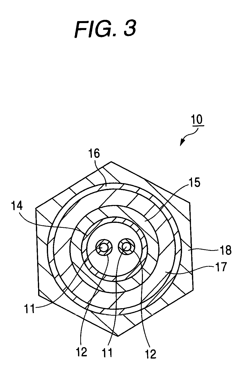
[0027]FIG. 1 is a cross-sectional view of a shielded cable prepared, using a first embodiment of a shielded cable-grounding structure of the invention, FIG. 2 is a cross-sectional view of the shielded cable of FIG. 1, FIG. 3 is a cross-sectional view of a modified example of the shielded cable-grounding structure of FIG. 1, and FIG. 4 is a cross-sectional view of another form of shielded cable.

[0028]As shown in FIG. 1, the shielded cable 10, incorporating the first embodiment of the shielded cable-grounding structure of the invention, comprises a pair of core portions 11 (each comprising a conductor), core covering portions 12 covering the core portions 11, respectively, a braided wire 14 provided around the pair of core covering portions 12, and a resin insulating sheath 15 provided around an outer periphery of the braided wire 14 to cover the core portions 11, the core covering portions 12 and the braided wire 14.

[0029]A first feature of the shielded cable 10 resides in the fact t...

second embodiment

[0041]Next, a second embodiment of a shielded cable-grounding structure of the invention will be described with reference to FIGS. 5 and 6. Those constituent elements and so on, corresponding to those of the shielded cable 10 described above, will be designated by identical or like reference numerals, respectively, and explanation thereof will be simplified or omitted.

[0042]FIG. 5 is a perspective view of a sleeve used in the second embodiment of the shielded cable-grounding structure of the invention, and FIG. 6 is a side-elevational view of a shielded cable having the sleeve of FIG. 5 mounted thereon.

[0043]As shown in FIG. 5, the sleeve 30, used in the second embodiment of the shielded cable-grounding structure of the invention, is made of an electrically-conductive material, and is formed into a generally U-shape. This sleeve 30 has slit-like press-contacting blades 32 and 32 formed respectively in upper edges of a pair of opposed side plates 31 and 31.

[0044]As shown in FIG. 6, i...


PUM


Abstract

In a structure for grounding a shielded cable, a braided wire is extended radially outwardly of core covering portions to form a flange portion, and an associated wire is connected to the flange portion by the use of sleeve members, thereby effecting the grounding.

Description

BACKGROUND OF THE INVENTION[0001]1. Field of the Invention[0002]This invention relates to a shielded cable-grounding structure for grounding a braided wire at an end of a shielded cable.[0003]2. Related Art[0004]There is known one conventional shielded cable-grounding structure in which one side portion, extending from a shielding terminal, is placed on an insulating sheath, and a resin chip is laid on the one side portion extending from the shielding terminal, and in this condition ultrasonic vibration is applied to fuse and dissipate at least the relevant portion of the insulating sheath, thereby forming a shielding conducting portion at which the one side portion, extending from the shielding terminal, is electrically connected to a braided wire of the shielded cable (see, for example, JP-A-11-135167).[0005]There is known another conventional shielded cable-grounding structure in which a shielding layer of a shielded cable is turned back on an outer periphery of an insulating she...

Claims


Application Information

Patent Timeline
Patent Type & Authority Patents(United States)
IPC IPC(8): H02G15/02
CPCH01R9/0512H01R4/2454H01R9/032H01R13/65912
Inventor ASAKURA, NOBUYUKISAKAGUCHI, TADAHISA
Owner YAZAKI CORP
Why Eureka
Try Eureka