Device for attenuating the stroke of the needle in pressure-controlled fuel injectors

a technology of pressure-controlled fuel injectors and needles, which is applied in the direction of fuel injection apparatus, fuel feed system, spraying apparatus, etc., can solve the problems of inability to reliably ensure the stability of injection quantities to be injected into the combustion chamber, the inability to achieve very small preinjection quantities, etc., to achieve favorable effect on emissions figures, high hydrocarbon values as well as soot development, and improve the minimum quantity capacity ratio ratio ratio ratio ratio ratio ratio ratio ratio ratio ratio ratio ratio ratio ratio ratio ratio ratio ratio ratio ratio ratio ratio ratio ratio ratio ratio ratio ratio ratio ratio ratio ratio ratio ratio ratio ratio ratio ratio ratio ratio ratio ratio ratio ratio ratio ratio ratio ratio ratio ratio ratio ratio ratio ratio ratio ratio ratio ratio ratio ratio ratio ratio ratio ratio ratio ratio ratio ratio ratio ratio ratio ratio ratio ratio ratio ratio ratio ratio ratio ratio ratio ratio ratio ratio ratio ratio ratio ratio ratio ratio ratio ratio ratio ratio ratio ratio ratio ratio ratio ratio ratio ratio ratio ratio ratio ratio ratio ratio ratio ratio ratio ratio ratio ratio ratio ratio ratio ratio ratio ratio ratio ratio ratio ratio ratio ratio ratio ratio ratio ratio ratio ratio ratio ratio ratio ratio ratio ratio ratio ratio ratio ratio ratio ratio ratio ratio ratio ratio ratio ratio ratio ratio ratio ratio ratio ratio ratio ratio ratio ratio ratio ratio ratio ratio ratio ratio ratio ratio ratio ratio ratio ratio ratio ratio ratio ratio ratio ratio ratio ratio ratio ratio ratio ratio ratio ratio ratio ratio ratio ratio ratio ratio ratio ratio ratio ratio ratio ratio ratio ratio ratio ratio ratio ratio ratio ratio ratio ratio ratio ratio ratio ratio ratio ratio ratio ratio ratio ratio ratio ratio ratio ratio ratio ratio ratio ratio ratio ratio ratio ratio ratio ratio ratio ratio ratio ratio ratio ratio ratio ratio ratio ratio ratio ratio ratio ratio ratio ratio ratio ratio ratio ratio ratio ratio ratio ratio ratio ratio ratio ratio ratio ratio ratio ratio ratio ratio ratio ratio ratio ratio ratio ratio ratio ratio ratio ratio ratio ratio ratio ratio ratio ratio ratio ratio ratio ratio ratio ratio ratio ratio ratio ratio ratio ratio ratio ratio ratio ratio ratio ratio ratio ratio ratio ratio ratio ratio ratio ratio ratio ratio ratio ratio ratio ratio ratio ratio ratio ratio ratio ratio ratio ratio ratio ratio ratio ratio ratio ratio ratio ratio ratio ratio ratio ratio ratio ratio ratio ratio ratio ratio ratio ratio ratio ratio ratio ratio ratio ratio ratio ratio ratio ratio ratio ratio ratio ratio ratio ratio ratio ratio ratio ratio ratio ratio ratio ratio ratio ratio ratio ratio ratio ratio ratio ratio ratio ratio ratio ratio ratio ratio ratio ratio ratio ratio ratio ratio ratio ratio ratio ratio ratio ratio ratio ratio

Inactive Publication Date: 2007-09-25
ROBERT BOSCH GMBH
View PDF4 Cites 7 Cited by
  • Summary
  • Abstract
  • Description
  • Claims
  • Application Information

AI Technical Summary

Benefits of technology

[0012]With the device for injecting fuel proposed according to the invention, the opening speed of an injection valve member, such as a nozzle needle, can be damped without causing an impairment to fast closure of the injection valve member. Opening of an injection valve member that takes place at a reduced opening speed improves the minimum-quantity capability of a fuel injector considerably. If short injection intervals can be attained, then minimum quantities can be effected even in the context of multiple preinjections into the combustion chamber of an internal combustion engine.
[0013]The embodiment proposed according to the invention has no effect on a rapidly proceeding closing event of the injection valve member. Fast closure of the injection valve member has a favorable effect on emissions figures for a self-igniting internal combustion engine, since in an advanced stage of combustion, no further fuel reaches the combustion chamber of the engine. The fuel located in the combustion chamber can be converted completely; excessively high hydrocarbon values as well as soot development are suppressed by a fast closure of the injection valve member. A fast needle closure also promotes a shallow course of the characteristic curves for quantity of the fuel to be injected into the combustion chamber in the ballistic mode of the injection valve member, or in other words during the reciprocating motion between its upper stop and its seat at the combustion chamber. A shallow course of the characteristic quantity curve also increases the metering precision of the fuel to be introduced into the combustion chamber considerably, since deviations in terms of the triggering of the injection valve member do not cause a major change in the quantity of fuel to be injected. In contrast to this, deviations in the triggering of the injection valve member when the characteristic quantity curves have a steep slope cause these deviations to be associated with a major increase in the quantity of fuel injected into the combustion chamber of a self-igniting internal combustion engine.
[0014]The embodiment of the proposed device for damping an injection valve member is especially advantageous if it is provided with a further filling path. This makes it possible for a damping element to return to its outset position very quickly, and hence a damping action, that is, a reduction in the opening speed of the injection valve member, is attained and hence multiple injections in rapid succession can be realized, for instance in a double preinjection.
[0015]If the device proposed according to the invention is used in a pressure-boosted fuel injector, the result is an injection system with high injection pressure, good hydraulic efficiency, and greatly improved minimum quantity capability. The proposed device for stroke damping of an injection valve member is moreover usable in other pressure-controlled injection systems, such as unit fuel injectors, pump-line-nozzle units, and distributor injection pumps, as well as in common rail systems with fuel injectors without a pressure booster.

Problems solved by technology

For reasons of strength, the feasible pressure level in common rail injection systems in use today is limited to about 1600 bar.
In pressure-controlled common rail injection systems with a pressure booster, the problem arises that the stability of injection quantities to be injected into the combustion chamber, and especially the realization of very small preinjection quantities, which are required in a preinjection, is not reliably assured.

Method used


Image

  • Device for attenuating the stroke of the needle in pressure-controlled fuel injectors
  • Device for attenuating the stroke of the needle in pressure-controlled fuel injectors
  • Device for attenuating the stroke of the needle in pressure-controlled fuel injectors

Examples


Embodiment Construction

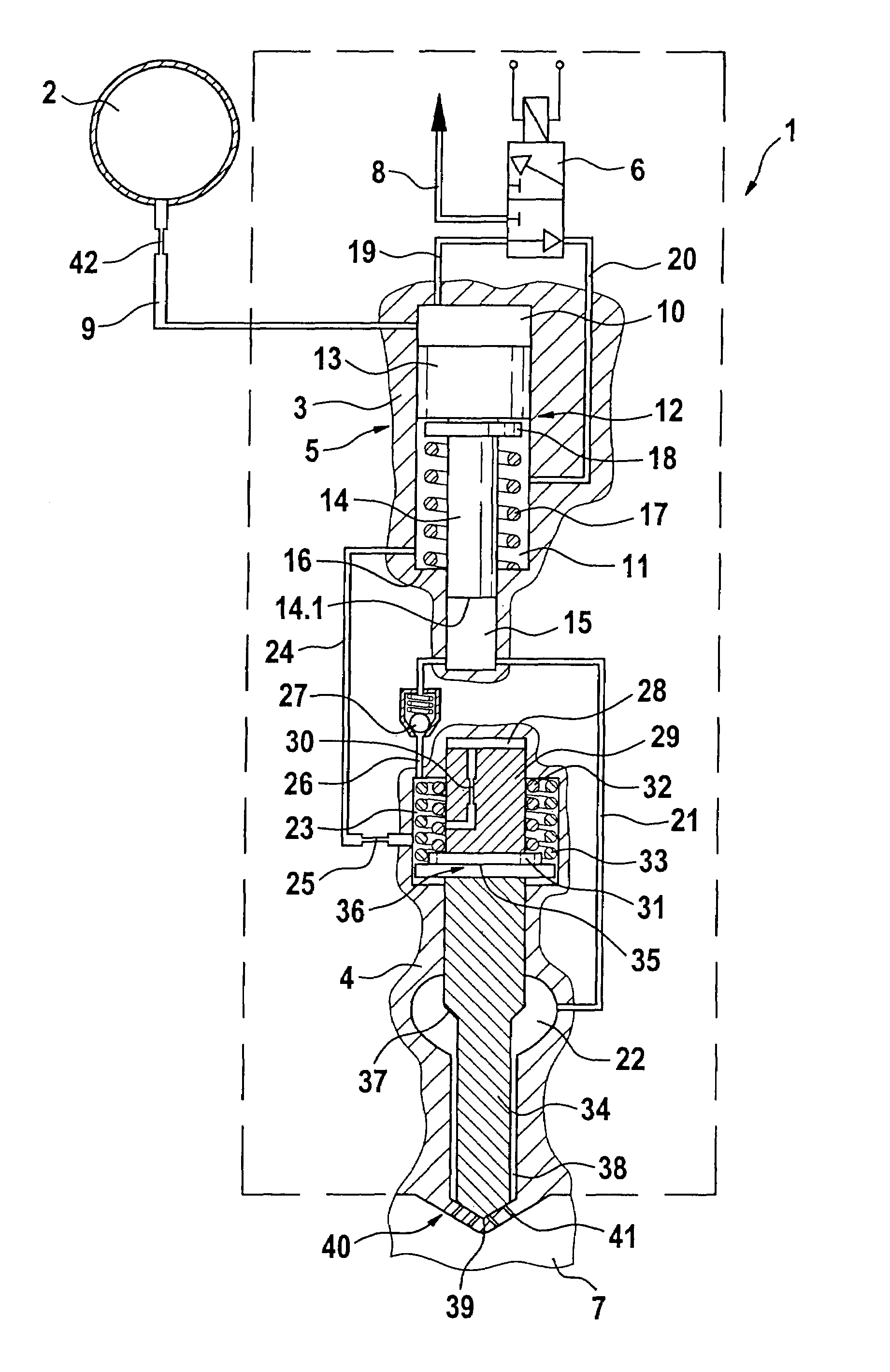
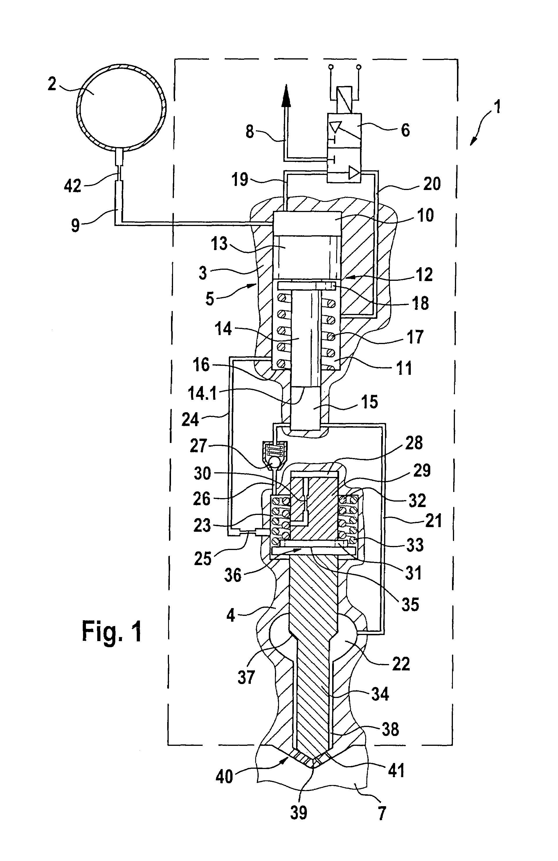
[0019]In FIG. 1, the first variant embodiment of a device for stroke damping of an injection valve member can be seen, with a damping element which includes a filling path for a hydraulic damping chamber.

[0020]The description of the device for damping the reciprocating motion of an injection valve member according to the invention will be made in conjunction with a fuel injector with a pressure booster. The proposed device for damping the reciprocating motion can also be employed in other fuel injection systems, such as unit fuel injector systems and pump-line nozzle systems, distributor injection pumps, and high-pressure reservoir injection systems (common rail injection systems), whose fuel injectors do not include a pressure booster.

[0021]The pressure-boosted fuel injector 1 shown in FIG. 1 is supplied with fuel at high pressure via a high-pressure reservoir 2 (common rail), shown only schematically here. From the interior of the high-pressure reservoir 2, a supply line 9 extends...


PUM


Abstract

The invention relates to a device for injecting fuel into a combustion chamber of an internal combustion engine, and which includes a fuel injector which can be acted upon by fuel at high pressure via a high-pressure source and is actuatable via a metering valve. Associated with the injection valve member is a damping element, which is movable independently of it and defines a damping chamber. The damping element has at least one overflow conduit for connecting the damping chamber to a further hydraulic chamber.

Description

CROSS-REFERENCE TO RELATED APPLICATIONS[0001]This application is a 35 USC 371 application of PCT / DE 03 / 01101 filed on Apr. 3, 2003.BACKGROUND OF THE INVENTION[0002]1. Field of the Invention[0003]For supplying combustion chambers of self-igniting internal combustion engines with fuel, both pressure-controlled and stroke-controlled injection systems may be used. As the fuel injection systems, not only unit fuel injectors and pump-line-nozzle units but also common rail injection systems may be used. Advantageously, common rail injection systems (common rails) make it possible to adapt the injection pressure to the engine load and rpm. To attain high specific outputs and to reduce emissions from the engine, the highest possible injection pressure is generally required.[0004]2. Description of the Prior Art[0005]For reasons of strength, the feasible pressure level in common rail injection systems in use today is limited to about 1600 bar. To increase the pressure further in common rail in...

Claims


Application Information

Patent Timeline
Patent Type & Authority Patents(United States)
IPC IPC(8): F02M47/02B05B1/30F02M45/00F02M59/00F02M61/10F02M47/00F02M57/02F02M61/16F02M61/20F02M63/00
CPCF02M47/027F02M57/025F02M57/026F02M61/205F02M2200/304
Inventor MAGEL, HANS-CHRISTOPH
Owner ROBERT BOSCH GMBH
Why Eureka
Try Eureka