Display device comprising a luminous element with an emission characteristic of controllable solid angle

a technology of luminous elements and light guides, which is applied in the direction of light control, spectral modifiers, microscopes, etc., can solve the problems of limited signal production and optical crosstalk, and achieve the effect of simple and cost-effective design

Inactive Publication Date: 2007-09-25
SIEMENS AG
View PDF6 Cites 22 Cited by
  • Summary
  • Abstract
  • Description
  • Claims
  • Application Information

AI Technical Summary

Benefits of technology

[0004]It is an object of the invention to provide a display unit of simpler and more cost-effective design.
[0006]The display unit therefore has a spatially differentiating light source that can be controlled by a controlling or regulating unit. It is thereby possible to supply various display surfaces with a light signal from a single luminous element. In one embodiment, the display surfaces are the outcoupling locations of the light guide. In another design, projection surfaces are provided onto which light emerging from the light guide falls. In a compact design of the display device, the projection surfaces are connected directly to the light guide. They can, however, likewise be realized as separate components. The same holds for the light entrance surfaces of the light guide, which are adapted to the optogeometrical conditions of the light guide and are positioned in accordance with the light source.
[0007]In an advantageous embodiment, the light guide has light channels that direct the incoupled light onto the appropriate display or projection surfaces. Possible problems arising from signals that produce optical crosstalk are limited in the simplest case by optical separation of the light channels, for example, by introducing a non-transmissive layer. However, additional optical channels made from glass or glass fibers and introduced into the light guide are also conceivable. They permit the light to be guided to the projection surface without interference.
[0011]Luminous elements having a sufficiently short wavelength, for example, UV light sources, render it possible to use projection surfaces equipped with wavelength transmitters to provide the light signal with different colors. Light with a wavelength of 400-800 mm is denoted as UV light. Phosphor and other so-called luminous materials whose activator centers emit the energy radiated by the luminous element with the desired color are used as frequency converters. It is also conceivable to use so-called silicon nanocrystals that emit different light of defined wavelengths after irradiation with UV light. Use in a dial is particularly advantageous here.

Problems solved by technology

Possible problems arising from signals that produce optical crosstalk are limited in the simplest case by optical separation of the light channels, for example, by introducing a non-transmissive layer.

Method used


Image

  • Display device comprising a luminous element with an emission characteristic of controllable solid angle
  • Display device comprising a luminous element with an emission characteristic of controllable solid angle
  • Display device comprising a luminous element with an emission characteristic of controllable solid angle

Examples


Embodiment Construction

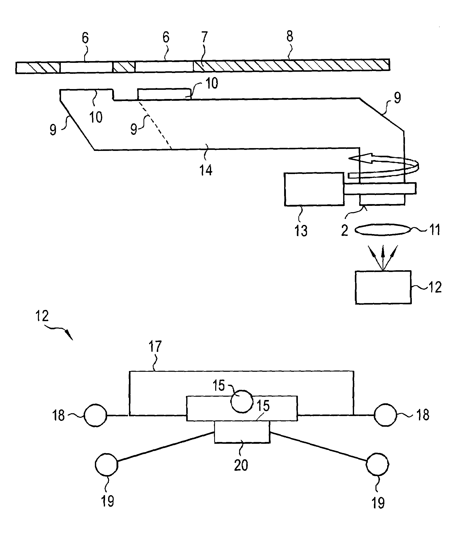
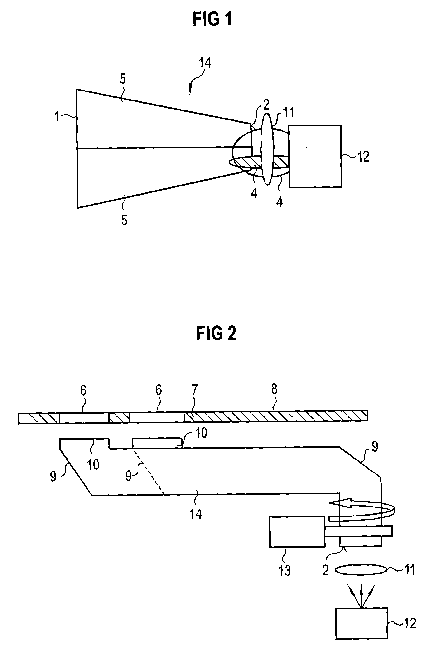
[0017]FIG. 1 illustrates a first embodiment of a display device according to the invention. Provided at the beginning of a beam path is a luminous element 12 that, depending on how it is driven, can produce a spatially different distribution of light cones, i.e., a different emission characteristic. By way of example, FIG. 1 shows two light cones 4 that, of course, cannot be produced simultaneously, but are illustrated jointly in FIG. 1 for illustrative purposes. A first light cone is narrow and therefore strikes a light entrance region 2 of a light guide 14 such that only a portion of the light entrance region 2 is irradiated by the light cone 4. Formed in the light guide 14 are two light channels 5 that are optically separated from one another, for example, by a reflecting layer. Instead of a reflecting layer between the two light channels 5 of the light guide 14, it is also conceivable to provide other non-transmissive or only partly transmissive layers, for example, a layer that...


PUM


Abstract

The invention relates to a display device including a luminous element and a light guide which has coupling locations and decoupling locations and transports a light signal that is emitted by the luminous element. The inventive luminous element has a radiation characteristic, the solid angle of which can be controlled.

Description

CROSS REFERENCE TO RELATED APPLICATIONS[0001]The present application is a continuation of international application PCT / DE03 / 002064, filed Jun. 20, 2003, which designated the United States, and further claims priority to German patent application DE10234124.9, filed Jul. 26, 2002, the both of which are herein incorporated by reference.BACKGROUND OF THE INVENTION[0002]The invention relates to a display device comprising a luminous element and a light guide having incoupling and outcoupling locations, the light guide being able to transport a light signal emerging from the luminous element.[0003]In display devices of this type, signals are displayed on a projection surface by means of a differentiating optical signal transmitter via an optically conducting element. In such displays, individual light-emitting elements, or an electronic display, are used. Examples of the application of such display devices are multistatus displays in tacographs or car radios that display a number of dis...

Claims


Application Information

Patent Timeline
Patent Type & Authority Patents(United States)
IPC IPC(8): F21V33/00B60K35/00B60Q3/00B60Q3/04F21V8/00G01D13/26
CPCB60K35/00B60Q3/005B60Q3/008B60Q3/044G01D13/265B60K37/02B60K2350/2034B60Q3/66B60Q3/68B60Q3/14B60K2370/331B60K2370/6992
Inventor FORD, GARYWOLF, JUERGEN
Owner SIEMENS AG
Why Eureka
Try Eureka