Bottling or container filling machine and other rotary bottle or container handling machines in a bottling or container filling plant and a drive therefor

a technology of rotary bottle or container and filling machine, which is applied in the direction of synchronising machines, liquid handling, transportation and packaging, etc., can solve the problems of increasing the susceptibility of the entire system to faults, requiring or wishing regular maintenance, and complex design, so as to eliminate the need or desire for a gearbox, reduce the susceptibility of the overall system to faults, and reduce the maintenance intensity.

Inactive Publication Date: 2012-11-06
INA DRIVES & MECHATRONICS +1
View PDF17 Cites 4 Cited by
  • Summary
  • Abstract
  • Description
  • Claims
  • Application Information

AI Technical Summary

Benefits of technology

[0015]An object of the present application is to create a drive for the described rotary machines that has a simpler and more cost-effective design yet maintains the same open and closed-loop control precision while simultaneously or substantially simultaneously being less susceptible to wear and faults.SUMMARY
[0017]A drive of this design completely eliminates the need or desire for a servomotor with a gearbox. Instead a collar with permanent magnets or electromagnets placed in regular intervals is arranged at the rotating machine component, for example at the location where the gearing was arranged previously. Arranged opposite to this on the stationary component of the machine is an electromagnetic stator, such as is used in a modified form in linear electric drives. The stator is bent and its radius is matched to the radius of the magnetic collar. The stator overlaps only a subsector of the rotating magnetic collar and / or a portion of a subsector of the rotating magnetic color. On the inside of the stator is a coil configuration, which enables a tangential force to be exerted against the opposing magnets, setting these together with the entire rotating component of the machine into motion. The size of the stator as well as the number and configuration of the internal coils is a function of the size and the required or desired forces and speeds. The moments generated and the resulting speeds can be controlled precisely or generally and independently as a function of the parameters of the field generated by the coils, such as field strength and field frequency.
[0021]The drive according to the present application is significantly smaller and more compact, and completely eliminates the need or desire for a gearbox. Furthermore, it comprises no moving parts other then the rotating machine component and is mounted in an area of the machine that is usually dry, so that it is not exposed to liquids or cleaning agents, which significantly reduces the fault susceptibility and maintenance intensity of the overall system.

Problems solved by technology

Disadvantageous here is the complicated configuration of the overall configuration because of the need or desire for a gearbox, which must or should work very precisely or generally to satisfy the requirements described above and thus must or should be very complex in design.
This also increases the susceptibility of the entire system to faults and requires or desires regular maintenance.
Because such systems are frequently operated in conjunction with large quantities of liquids, the entire configuration must or should be encapsulated to be watertight, which further increases the complexity.
Furthermore, it comprises no moving parts other then the rotating machine component and is mounted in an area of the machine that is usually dry, so that it is not exposed to liquids or cleaning agents, which significantly reduces the fault susceptibility and maintenance intensity of the overall system.

Method used


Image

  • Bottling or container filling machine and other rotary bottle or container handling machines in a bottling or container filling plant and a drive therefor
  • Bottling or container filling machine and other rotary bottle or container handling machines in a bottling or container filling plant and a drive therefor
  • Bottling or container filling machine and other rotary bottle or container handling machines in a bottling or container filling plant and a drive therefor

Examples


Embodiment Construction

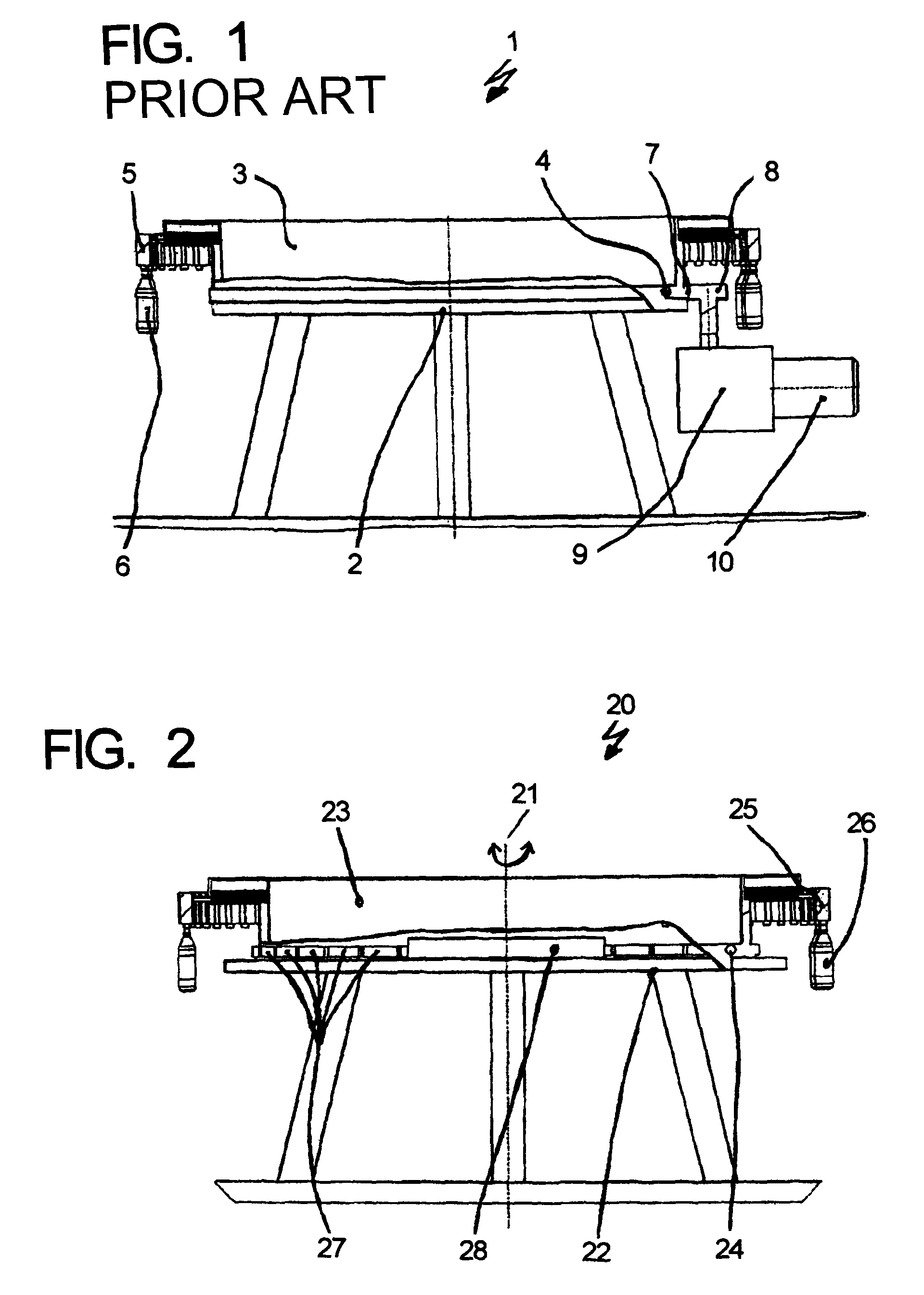
[0031]A rotary machine of the prior art, designated as a whole with 1, is shown in detail in FIG. 1. It has a stationary machine component 2 and a rotating machine component 3, which are connected together by means of a ball bearing rotary connector. Arranged on the outside of the rotating component are filling stations 5, with which beverage bottles 6 are filled with product.

[0032]Arranged on the outside of the ball bearing rotary connector 4 connected to the rotating machine component 3 is gearing 7, in which a pinion 8 driven by a servomotor 10 via a gearbox 9 engages. The rotation component of the machine is driven and its speed controlled by supplying an appropriate current to the servomotor 10.

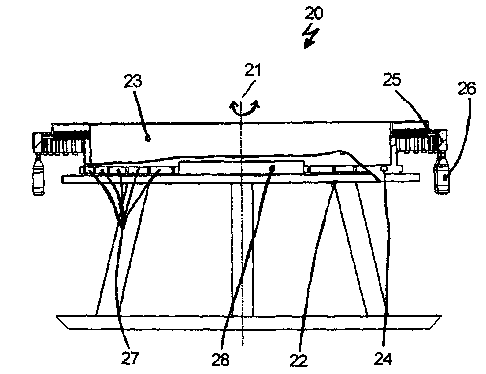
[0033]The drive according to the present application is shown in detail in FIG. 2. Here, too, the container handling machine, designated as a whole with 20, has a stationary machine component 22 and a rotating machine component 23 that can be rotated around a center shaft 21. There is a ...


PUM


Abstract

A rotary container handling machine which has a stationary frame and a turntable supported thereby, which turntable has container handling devices for handling containers. The turntable is rotated by a drive. The drive comprises an encircling collar with a plurality of magnets, and at least one stator which overlaps one subsector of the collar to permit rotation of the turntable by an electromagnetic field generated by the at least one stator. The collar is disposed on either the stationary frame or the turntable, while the at least one stator is disposed on the other.

Description

CONTINUING APPLICATION DATA[0001]This application is a Continuation-In-Part application of International Patent Application No. PCT / EP2007 / 007226, filed on Aug. 16, 2007, which claims priority from Federal Republic of Germany Patent Application No. 10 2006 039 090.3, filed on Aug. 19, 2006. International Patent Application No. PCT / EP2007 / 007226 was pending as of the filing date of this application. The United States was an elected state in International Patent Application No. PCT / EP2007 / 007226.BACKGROUND[0002]1. Technical Field[0003]The present application relates to a bottling or container filling machine and other rotary bottle or container handling machines in a bottling or container filling plant and a drive therefor, and further to a drive for rotary machines having a stationary and a rotating component.[0004]2. Background Information[0005]Background information is for informational purposes only and does not necessarily admit that subsequently mentioned information and publica...

Claims


Application Information

Patent Timeline
Patent Type & Authority Patents(United States)
IPC IPC(8): H02K41/03
CPCB67C3/22B67C7/004H02K41/031H02K2201/15
Inventor WILHELM, LOTHARWOLF, UWEALBRECHT, CHRISTIANSCHMID, GUNTER
Owner INA DRIVES & MECHATRONICS
Why Eureka
Try Eureka